Coefficient evidence
Wetness, contamination, temperature, speed, wear, and pressure can reduce or vary friction during a stop. A catalog value outside its test domain is not a conservative input by default.
Physics and mechanics
Compare two friction coefficients using ideal stopping distance, a declared safety factor, available distance, and campaign energy.
TWO-SURFACE STOPPING SCREEN
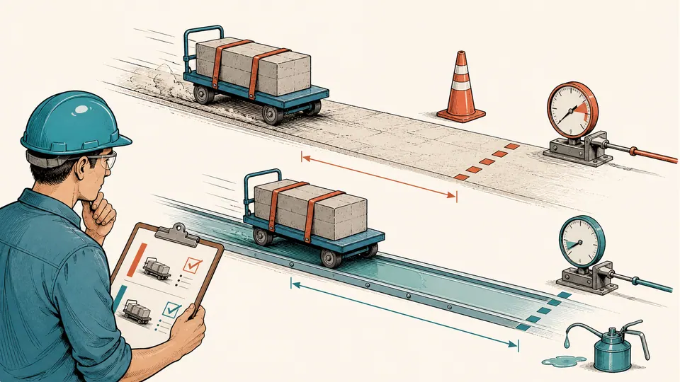
Higher friction shortens an idealized stop, but a screening result is not a brake certification. This calculator compares two surface scenarios at the same mass and speed, protects each distance with an explicit factor, and shows the available margin.
TWO-SURFACE STOPPING SCREEN
A scenario passes this screen only when available distance exceeds its safety-factored ideal distance. Neither label is a brake or surface approval.
| Scenario | Coefficient | Ideal distance | Safety factor | Protected distance | Margin |
|---|
DETAILED CALCULATION PROCESS
dideal = v²/(2 mu g); dprotected = SF x dideal; margin = davailable - dprotected; Ecampaign = n mv²/2
Apply the work-energy stopping relation independently to each coefficient, multiply each distance by the same declared factor, and compare with one measured usable distance.
| Symbol | Meaning | Unit | Default-page basis |
|---|---|---|---|
| v | Initial speed | m/s | entered speed |
| mu | Kinetic friction coefficient | dimensionless | scenario-specific value |
| g | Gravity | m/s² | entered value |
| dideal | Ideal friction-only stopping distance | m | v² ÷ (2 mu g) |
| SF | Distance protection factor | dimensionless | entered factor |
| margin | Usable minus protected distance | m | davailable − SF × dideal |
RESULT INTERPRETATION
Ideal stopping distance uses a constant kinetic coefficient and immediate friction-only deceleration. Protected distance multiplies that ideal result by the entered factor. A positive margin means the protected distance fits inside the declared usable distance under these assumptions; zero is a boundary with no modeled clearance.
Campaign energy depends on mass and stop count even though mass cancels from the ideal stopping-distance equation. Read distance and energy together: one screens available travel, while the other indicates the mechanical energy that braking and thermal systems must repeatedly manage.
DECISION BOUNDARY
A scenario passes this screen only when available distance exceeds its safety-factored ideal distance. Neither label is a brake or surface approval.
Wetness, contamination, temperature, speed, wear, and pressure can reduce or vary friction during a stop. A catalog value outside its test domain is not a conservative input by default.
SENSITIVITY AND STRESS TESTING
Exclude obstructions and any reaction or actuation travel not represented by the model. Measuring total room length can create false margin.
The factor must come from an applicable design or screening basis. Using the same factor isolates coefficient effects but does not prove both scenarios meet governing requirements.
HOW TO USE THIS CALCULATOR
SUBJECT FOUNDATIONS
MODEL BOUNDARY
Apply the work-energy stopping relation independently to each coefficient, multiply each distance by the same declared factor, and compare with one measured usable distance.
DECISION DEPTH
Detection, control, actuator, or human response can add travel not represented in the friction-only equation.
Water, heat, fade, contamination, lock-up, and speed dependence can invalidate one constant value.
The correct design margin may be load-, hazard-, and jurisdiction-specific. Record its source rather than selecting a convenient number.
REAL USE CASES
Maintenance screens whether an oil-contaminated coefficient removes the available stopping margin and flags the need for testing.
A design team compares two lining values at identical speed before commissioning instrumented stop trials.
TERMS USED ON THIS PAGE
EVIDENCE TO RETAIN
Retain speed measurement, mass, usable-distance survey, surface descriptions, coefficient test or source, temperature and contamination state, factor basis, stop count, omitted response delays, and any instrumented validation records.
LIMITS AND EXCLUSIONS
RELIABLE SOURCES
QUESTIONS SPECIFIC TO THIS CALCULATION
In the simplified work-energy equation both kinetic energy and friction force are proportional to mass, so it cancels.
No. It controls energy, forces on equipment, thermal load, and many real brake behaviours excluded here.
Yes only with evidence applicable to the actual material, speed, load, temperature, and contamination condition.
No. It only has the larger or passing margin under this screening model.
Add it through a more complete stopping model or subtract it from usable distance with a documented basis.
A common factor isolates the coefficient difference. If governing factors differ, compare under the actual requirements and explain why.
Use the unrounded value. An exactly zero margin is a no-clearance boundary; a rounded zero can hide a small pass or shortfall.
Both kinetic energy and Coulomb friction scale with mass in the ideal equation, but mass still controls energy, brake load, heat, structure, and many excluded dynamics.
Only when different governing bases require them. Then document each basis and recognize that the comparison no longer isolates friction coefficient alone.
Do not tune the coefficient or factor to force a pass. Revisit usable distance, speed, surface evidence, response delay, and the applicable engineered stopping requirement.
IMPORTANT BOUNDARY
This idealized result is not a brake, vehicle, machinery, amusement-device, lifting-system, or occupational-safety certification. Use applicable standards, measured tests, and qualified engineering review.