A straw looks bent in water because light does not travel through water and air at the same speed. Snell’s law makes that visual fact calculable. It predicts the direction of a transmitted ray at one interface—not its brightness, a lens’s focal length, or the quality of an image formed by many surfaces.
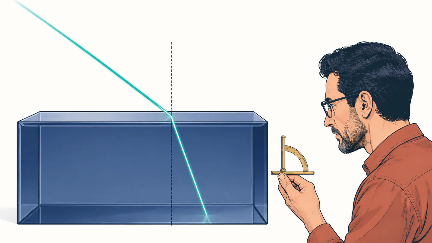
n1 sin θ1 = n2 sin θ2Both θ angles are measured from the normal: the perpendicular to the boundary, not from the surface itself.
What each symbol carries
Dimensionless. Each value belongs to a stated material, wavelength, temperature, and optical condition.
Angle from the normal on the side where the ray arrives. Use radians in radian-based software calls.
Angle from the normal in the second medium. It is only defined for a propagating transmitted ray.
For the simple phase-index picture, n = c/v; both speeds have units m s−1.
The dimensional check is deliberately plain: n and sin θ are dimensionless, so both sides are dimensionless. The physics is less plain. A larger refractive index corresponds, in the simple model, to a lower phase velocity. If n2 > n1, then sin θ2 < sin θ1 and the ray bends toward the normal. Swap the index step and it bends away.
Why the sines appear
One derivation starts with the physical path’s stationary travel time. Let a ray cross a flat boundary at a variable horizontal point x; its start and end are perpendicular distances a and b from that boundary, with total horizontal separation D. The travel time is:
t(x) = √(x² + a²)/v1 + √((D − x)² + b²)/v2dt/dx = 0 → sin θ1/v1 = sin θ2/v2n1 sin θ1 = n2 sin θ2Huygens’s construction reaches the same result from wave fronts: in equal time intervals, one side of a front advances a different distance after crossing the interface, yet the new front must stay continuous. Both explanations assume a sharp, stationary boundary and a ray or wave-front description that is sensible at the relevant scale.
Solve it in the useful direction
θ2 = sin−1((n1/n2) sin θ1)θ1 = sin−1((n2/n1) sin θ2)n2 = n1 sin θ1 / sin θ2θc = sin−1(n2/n1) for n1 > n2Every inverse-sine argument must lie between −1 and 1. Above 1 is not a calculator rounding problem. In the lossless ray model it says that no propagating transmitted ray can satisfy the boundary condition. At normal incidence both angles are zero, so index-solving forms divide by zero and cannot recover an index ratio from that one ray.
Worked example 1: air into glass
Take n1 = 1.000 for air, n2 = 1.500 for a stated ordinary-glass condition, and θ1 = 30.0°, measured from the normal:
So the refracted angle is 19.5° to three significant figures. It is smaller than 30.0°, as the higher-index destination requires. The equality check also gives n1 sin θ1 = (1.000)(0.500000) = 0.500000. The law gives direction only: real glass also reflects some light at the surface.
Worked example 2: water into air and the critical angle
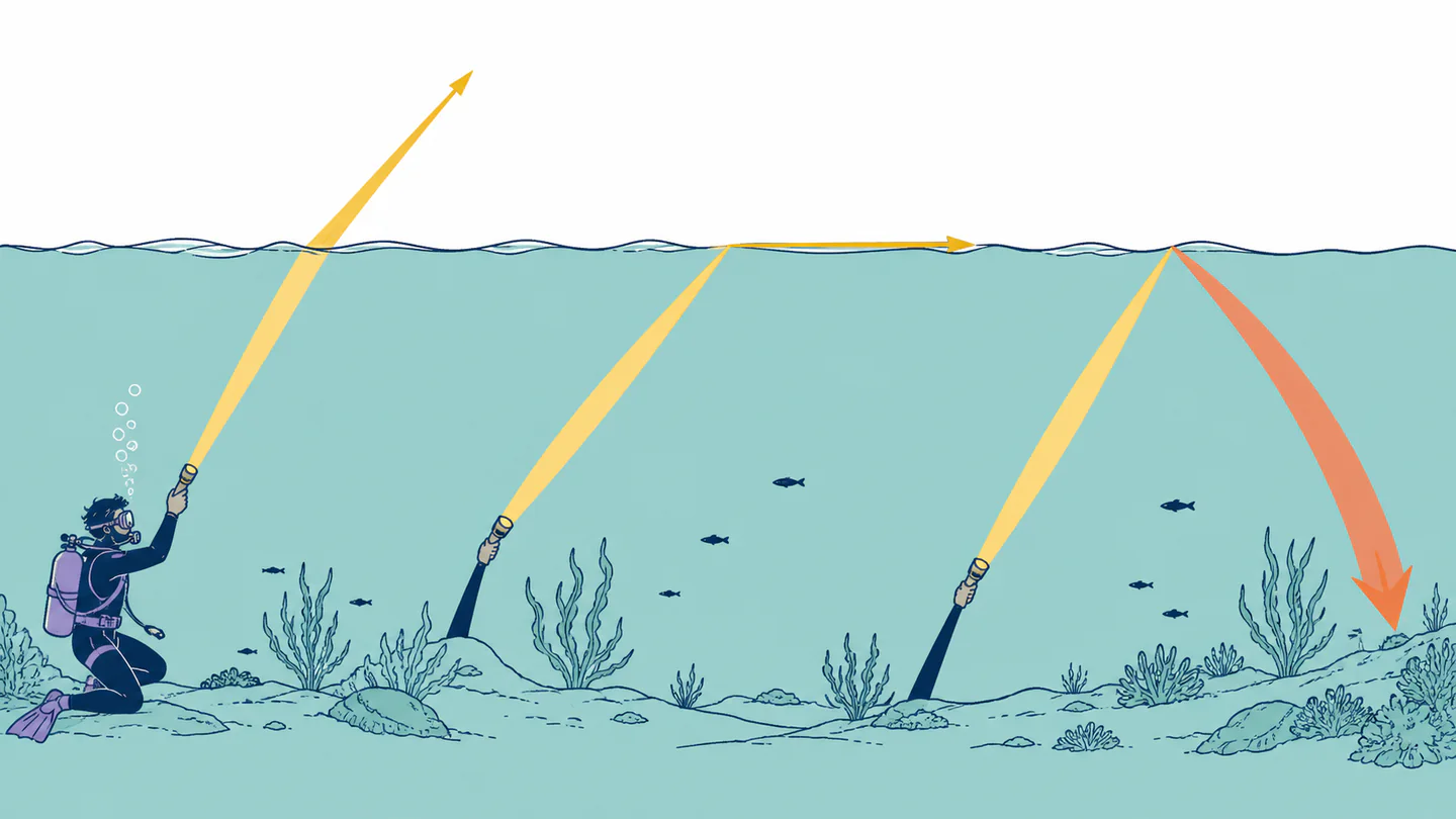
Use n1 = 1.333 for water and n2 = 1.000 for air at the stated wavelength and conditions. First, find the boundary angle:
θc = sin−1(1.000/1.333) = sin−1(0.750188) = 48.61°sin θ2 = (1.333)(sin 55.0°) = (1.333)(0.819152) = 1.091931.09193 > 1, so no real θ2: total internal reflectionAt 48.61°, the refracted ray would run along the boundary at 90° to the normal. At 55.0°, there is no propagating refracted ray in this ideal interface model; that is total internal reflection. Snell’s law has not failed—its domain check has told you which optical regime applies.
Error checks worth doing before you trust a result
A ray 20° to the surface is 70° to the normal. Substituting 20° changes the model.
n1 belongs to the incident side and n2 to the transmitted side; do not swap one without the other.
Most code-library sine functions expect radians. A degree value passed directly produces a wrong numerical sine.
Reflectance, transmission, absorption, and polarization require more than Snell’s direction relation.
Where a single index is too simple
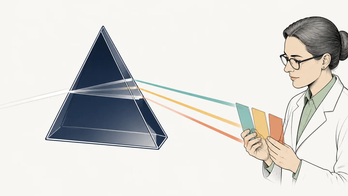
The scalar formula is most reliable at a locally flat, smooth boundary between homogeneous isotropic media. In a dispersive material, refractive index varies with wavelength and temperature; the National Institute of Standards and Technology measures exactly those dependencies. A prism therefore needs n(λ), not one rounded glass number for every color.
In birefringent crystals, polarization and propagation direction can select different indices and refracted directions. In graded-index materials, rays bend continuously rather than at one boundary. Rough, patterned, absorbing, nonlinear, moving, or time-varying interfaces may require scattering, diffraction, complex-index, or frequency-shift treatments. Near the critical angle, beam width, surface quality, and index uncertainty matter too.
Snell’s law is therefore a precise local tool. It can say where an ideal transmitted ray points once you define the media and the angle convention. It cannot, by itself, say how much light arrives there, whether the material data match the sample, or what an optical system will resolve.