EN

Engineering

Retaining Wall Sensitivity Calculator

Stress-test retaining-wall overturning and sliding factors under a paired demand increase.

RETAINING WALL SENSITIVITY

Show how a demand increase changes the governing wall factor

One sensitivity percentage is applied to both overturning and sliding demand so the adverse case is explicit and reproducible.

Decision boundary:For design teams stress-testing a documented paired demand increase; it is deterministic and does not estimate failure probability.

Base governing factor-
Adverse governing factor-
Demand increase-
Threshold status-

DECISION MAP

Retaining Wall Sensitivity Calculator evidence path

Use the adverse factor to decide whether demand uncertainty warrants a more detailed load model or additional resistance.
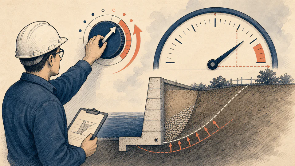
An engineer turns a retaining-wall demand dial upward while the governing safety-factor needle moves toward a review line.
Retaining Wall Sensitivity Calculator calculation ledgerUnrounded path and interpretation
CaseOverturning demand (kN*m/m)Sliding demand (kN/m)Overturning FSSliding FSGoverning FS

LIVE CALCULATION PROCESS

Formula, symbols, substitution, and final check

D_adverse = D_base(1 + d/100); FS_gov = min(M_R/M_O, R_SL/H_D)

The base and adverse rows use the same resistance values. Only demands change, making the sensitivity driver visible.

SymbolMeaningUnitCurrent input
MRResisting moment held constantkN*m/m820
RSLSliding resistance held constantkN/m510
MOBase overturning demandkN*m/m420
HDBase horizontal demandkN/m280
dDPaired demand increase%15
FSreqEntered adverse-case review thresholddimensionless1.5

    HOW TO USE

    Show how a demand increase changes the governing wall factor

    1. Enter the base resisting actions and the paired overturning and sliding demands.
    2. Set a non-negative demand increase that represents the documented uncertainty.
    3. Enter the review threshold used to interpret the adverse governing factor.
    4. Compare base and adverse mechanisms without changing resistance in the same scenario.
    5. Record the trigger for a full load model instead of treating the sensitivity as a code factor.

    SUBJECT FUNDAMENTALS

    Terms behind Retaining Wall Sensitivity Calculator

    Demand increase
    Paired action sensitivity
    Base factor
    Factor before sensitivity
    Adverse factor
    Factor after demand increase
    Resistance
    Stabilizing action held constant
    Governing mode
    Lower of two mechanisms

    CALCULATION METHOD

    Why this formula fits the topic

    D_adverse = D_base(1 + d/100); FS_gov = min(M_R/M_O, R_SL/H_D)

    The base and adverse rows use the same resistance values. Only demands change, making the sensitivity driver visible.

    DEEPER ANALYSIS

    Where professional judgement still matters

    Paired assumption

    Increasing both demands is conservative only for the declared uncertainty story.

    Resistance uncertainty

    A separate resistance reduction would be a different scenario.

    Decision use

    Sensitivity identifies what to verify; it does not set a code load.

    WORKED DECISION CASES

    Two realistic uses

    Paired surcharge screen

    The 820/420 and 510/280 base ratios govern at 1.821. A 15% increase to both demands reduces the governing factor to 1.584, which remains just above an entered 1.5 review threshold.

    Sensitivity trigger for fuller loading

    A 30% paired demand increase reduces the same 1.821 base factor to 1.401. The below-threshold result identifies the need for a full water, surcharge, and load-combination model rather than claiming failure probability.

    Technical glossary

    Sensitivity
    A deterministic change applied to the declared demand case.
    Demand factor
    One plus the entered percentage increase divided by 100.
    Adverse case
    The paired-demand row after applying the sensitivity.
    Overturning factor
    Resisting moment divided by adverse overturning moment.
    Sliding factor
    Base resistance divided by adverse horizontal drive.
    Trigger
    The documented condition that requires a fuller design check.

    EVIDENCE AND DATA LINEAGE

    What to retain with the result

    Retain the uncertainty source, base load combination, resistance calculation, and threshold.

    LIMITS AND EXCLUSIONS

    What this model does not establish

    • No probabilistic reliability, water-pressure, seismic, or global-stability analysis.
    • The demand increase is an assumption, not a measured probability.
    • Confirm the project-specific load combinations.

    RELIABLE SOURCES

    References for method and context

    FREQUENTLY ASKED QUESTIONS

    Retaining Wall Sensitivity Calculator questions

    Why change both demands together?

    The page models a declared paired uncertainty; use another model for independent changes.

    Can the increase be negative?

    No. Enter a non-negative adverse increase.

    Does resistance stay constant?

    Yes, by design; changing resistance needs a separate case.

    Is the result a reliability index?

    No, it is a deterministic ratio.

    What if the adverse case still passes?

    Retain the result and inspect other mechanisms not modeled here.

    Who approves the sensitivity?

    The project engineer under the governing standard.

    IMPORTANT NOTE

    Before relying on the exported result

    Sensitivity screen, not a final retaining-wall design.

    RELATED CALCULATORS

    Continue the decision with a neighboring check