Live calculation visualCurrent entered assumptions
Home & Construction
Gutter Load Calculator
Screen one simplified rectangular gutter section while preserving each load component and the hanger-spacing assumption.
GUTTER LINE-LOAD SCREEN
Turn water, ice, debris, and self-weight into a transparent hanger-spacing demand
Installers and designers can screen a simplified rectangular gutter section. The page reports component line loads, total run load, and an interior-hanger planning reaction; it does not rate hangers, fasteners, fascia, or the roof edge.
Interior hanger planning load—
Total line load—
Total run load—
Water component—
Ice component—
Layout hanger count—
TROUGH-TO-HANGER LOAD PATH
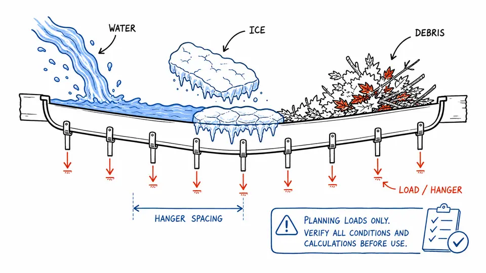
See mass enter the gutter and distribute across measured spacing
The section fill controls fluid weight per foot; spacing converts line load to a simplified interior reaction while end layout remains visible.
| Load component | Geometry/fraction | Density or rate | Line load | Run total |
|---|
How to use
Turn water, ice, debris, and self-weight into a transparent hanger-spacing demand
- Measure the profile and choose a conservative modeled width and depth.
- Enter mutually exclusive water and ice fill fractions.
- Use a documented ice-density assumption when ice is included.
- Add observed or specified debris and gutter self-weight per foot.
- Enter proposed hanger spacing and review component and total loads.
- Verify actual profile, end reactions, fasteners, fascia, snow/ice, wind, overflow, and manufacturer capacities separately.
GUTTER LOAD FUNDAMENTALS
Separate section geometry, fill state, line load, spacing, and hanger reaction
- Section area
- Simplified width times depth of the filled rectangle.
- Line load
- Weight distributed per foot of gutter.
- Fill fraction
- Share of modeled section occupied by water or ice.
- Interior reaction
- Approximate line load times hanger spacing.
- Load path
- Transfer through hanger, fastener, fascia, and framing.
CALCULATION METHOD
Build component line loads before assigning a hanger interval
Estimate water, ice, debris, and self-weight per unit length from entered geometry and densities, sum them, then multiply by spacing to obtain an interior planning reaction.
SECTION GEOMETRY
Actual profiles are not rectangles
K-style and half-round sections have curved geometry; use actual cross-section data when precision matters.
ICE AND DEBRIS
Ice is not simply frozen full water
Snow, melt, freeze, icicles, dams, thermal cycles, and blocked outlets create nonuniform loads beyond one fill fraction.
ATTACHMENT DESIGN
Demand is not rated capacity
Hanger, screw, fascia, connection spacing, edge distance, corrosion, substrate, and manufacturer tests govern allowable performance.
Detailed calculation process
Gutter load component ledger
The rectangular section area is multiplied by density and fill fraction. Debris and self-weight are added as line loads. Multiplying total line load by spacing estimates a typical interior share; end conditions and capacity are outside the model.
A = width×depth/144wwater = 62.4×A×water fraction; wice = ρice×A×ice fractionwtotal = wwater+wice+wdebris+wselfinterior hanger planning load ≈ wtotal×spacing/12
| Symbol | Meaning | Unit |
|---|---|---|
| A | Modeled full section area | ft² |
| ρ | Entered material density | lb/ft³ |
| w | Line load | lb/ft |
| spacing | Hanger interval | in |
| fill | Volume fraction | dimensionless |
| run | Gutter length | ft |
- Rectangle: 5×3/144 = 0.104167 ft².
- Full water: 62.4×0.104167 = 6.50 lb/ft.
- Add 1.50 debris and 1.00 gutter = 9.00 lb/ft.
- At 24 in spacing: 9.00×2 = 18.00 lb per interior interval.
- Run total: 9.00×50 = 450 lb.
- 26 layout hangers arise from 25 intervals plus an endpoint.
The live result cards and exact ledger above provide the final reconciliation for the current inputs.
Result interpretation
Hanger reaction is demand, not rated capacity
Load per hanger is the primary spacing screen, not a certified capacity. A zero ice result means the entered ice fraction is zero. Total run load is distributed mass; it is not one point force at a single fastener.
Visual interpretation
See mass enter the gutter and distribute across measured spacing
Fluid bands fill the section by entered fraction; load arrows scale with component weight and hanger markers with spacing. The visual is a load-path explanation, not a deformation or failure prediction.
EVIDENCE FOR THIS MODEL
Retain profile geometry, component assumptions, spacing, and attachment condition
Retain profile drawing, actual internal area, run and slope, fill scenario, water path, local ice/snow observations, debris maintenance condition, metal weight, hanger and fastener product data, fascia and framing condition, spacing layout, corners, outlets, and engineer/manufacturer review.
SCOPE AND LIMITATIONS
Why line-load arithmetic cannot approve hanger spacing
- Rectangular uniform fill and uniform spacing only.
- No snow bridging, icicles, impact, wind, thermal, ponding, clogged-outlet, corner, end, or dynamic effects.
- No hanger or fastener capacity is supplied.
- Water and ice fractions cannot exceed 100% combined.
KEY TERMINOLOGY
Gutter loading and attachment terms
- Pcf
- Pounds per cubic foot.
- Plf
- Pounds per linear foot.
- Tributary interval
- Length assigned to an interior hanger.
- Self-weight
- Weight of empty gutter and included hardware per foot.
- Debris load
- Entered nonfluid material weight per foot.
- Uniform load
- Idealized constant load along the run.
PRACTICAL DECISIONS
Full-water maintenance screen versus Ice-prone eave
Full-water maintenance screen
Use the water component to compare spacing, then verify drainage capacity so sustained full depth is not assumed acceptable.
Ice-prone eave
Treat the result as one scenario and obtain a project-specific roof-edge and connection assessment.
AUTHORITATIVE BASIS
References for gutter line-load screen
Important note
Do not approve hanger spacing or structural adequacy from this page. Verify actual profile, load cases, product ratings, fasteners, fascia, and framing.
Frequently asked questions
Why use 62.4 lb/ft³ for water?
It is the conventional density used by this planning conversion.
Can water and ice both be 100%?
No; the model rejects combined fill above the section volume.
Does closer spacing always solve the problem?
It lowers the simplified interior share but does not verify fasteners, fascia, end conditions, or installation.
Why add one hanger to interval count?
A straight run with n intervals has n+1 endpoints; actual layout must follow product instructions.
Can I enter half-round geometry?
Only by replacing the rectangle with an equivalent area outside this page; the inputs themselves model a rectangle.
Is this a structural calculator?
It is a demand screen, not a capacity or code design.