Live calculation visualCurrent entered assumptions
Home & Construction
Gutter Coverage Calculator
Connect an entered design storm to the limiting conveyance component instead of equating installed gutter length with hydraulic coverage.
ROOF CATCHMENT CAPACITY
Compare an entered design storm with the limiting gutter-and-downspout path
Designers and owners can convert roof catchment, rainfall intensity, and runoff coefficient to peak gallons per minute, then compare entered gutter and downspout capacities and expose unassigned roof edge.
Entered-storm status—
Peak runoff—
Limiting system capacity—
Capacity margin—
Hydraulic bottleneck—
Unassigned roof edge—
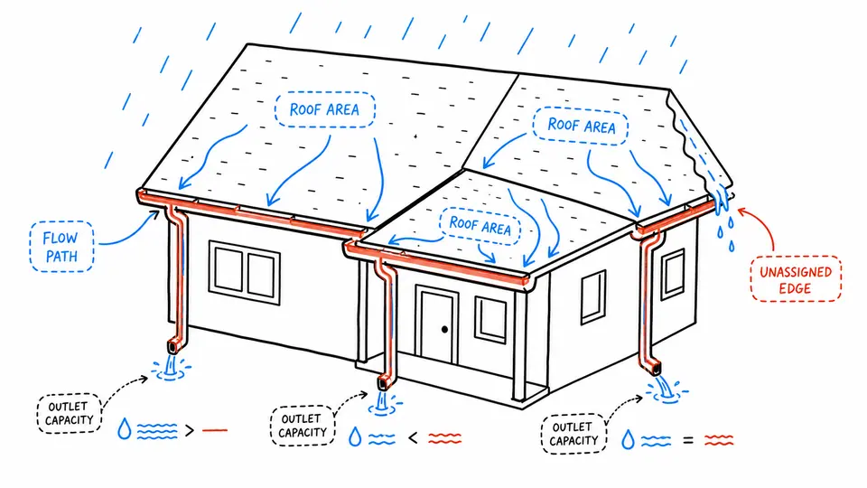
CATCHMENT-TO-OUTLET NETWORK
Trace rainfall, edge assignment, and the hydraulic bottleneck
Roof area becomes peak flow; two capacity gates show whether trough or downspouts limit the system, while unassigned edge remains outside the network.
| Stage | Input/basis | Flow or length | Margin | Interpretation |
|---|
How to use
Compare an entered design storm with the limiting gutter-and-downspout path
- Obtain the governing local rainfall intensity for the chosen duration and method.
- Measure served horizontal roof projection and identify every catchment.
- Enter a justified runoff coefficient.
- Enter gutter capacity for the actual profile, slope, length, and outlet condition.
- Enter downspout capacity and count for the same system.
- Compare the limiting capacity, margin, area per outlet, and unassigned edge; then apply the governing sizing standard.
ROOF DRAINAGE FUNDAMENTALS
Connect catchment area, design rainfall, runoff, edge assignment, and bottleneck capacity
- Catchment
- Roof area draining to the evaluated outlet system.
- Rainfall intensity
- Storm rate in inches per hour for a defined frequency and duration.
- Runoff coefficient
- Fraction used by the Rational Method.
- Peak flow
- Modeled runoff rate in gallons per minute.
- Bottleneck
- Smaller of gutter-run and combined-downspout capacity.
CALCULATION METHOD
Compare one storm demand with the weakest conveyance component
Use the Rational Method for entered peak runoff, assign demand to the gutter edge, compare it with entered gutter and downspout capacities, and report the smaller capacity as controlling.
DESIGN RAINFALL
Rainfall must match jurisdiction and risk
Intensity depends on location, duration, recurrence, climate data, and governing procedure; a convenient universal value is not defensible.
HYDRAULIC BOTTLENECK
Entered capacity is geometry-dependent
Profile, slope, length, roughness, outlet shape, end versus center outlet, elbows, and head condition affect published capacity.
EDGE ASSIGNMENT
Coverage is hydraulic and physical
Adequate gpm does not help an eave that has no trough or a catchment routed to the wrong outlet.
Detailed calculation process
Gutter coverage and capacity ledger
The Rational Method unit conversion produces peak flow from horizontal area, intensity, and coefficient. Conveyance is the minimum of entered gutter and combined downspout capacities. Physical edge assignment is checked separately.
Q = 0.0103896×C×i×Adownspout total = count×capacity eachsystem capacity = min(gutter capacity, downspout total)margin = system capacity−Q; max area = capacity/(0.0103896Ci)
| Symbol | Meaning | Unit |
|---|---|---|
| Q | Peak runoff | gpm |
| C | Runoff coefficient | dimensionless |
| i | Rainfall intensity | in/hr |
| A | Horizontal catchment area | ft² |
| capacity | Entered conveyance rate | gpm |
| edge | Roof perimeter assigned to gutter | ft |
- Peak flow: 0.0103896×1×4×2,000 = 83.1168 gpm.
- Three downspouts at 25 gpm provide 75 gpm combined.
- System capacity is min(100,75) = 75 gpm.
- Margin = 75−83.1168 = −8.1168 gpm.
- The downspouts are the entered bottleneck.
- 180−150 = 30 ft of roof edge remains unassigned.
The live result cards and exact ledger above provide the final reconciliation for the current inputs.
Result interpretation
Status applies only to the entered storm and capacity data
A capacity shortfall means the entered limiting capacity is below modeled peak runoff; it is not a flood prediction. A positive margin applies only to the entered storm and capacities. Unassigned edge is a physical coverage warning independent of gpm.
Visual interpretation
Trace rainfall, edge assignment, and the hydraulic bottleneck
Catchment color flows to the two entered capacity gates; the narrower gate is labeled bottleneck. Edge coverage is drawn separately because length and flow use different units. The graphic does not simulate transient water depth.
EVIDENCE FOR THIS MODEL
Retain catchment geometry, rainfall source, runoff basis, product capacity, and outlet allocation
Retain NOAA/local rainfall source, duration/frequency, roof plan and horizontal catchments, coefficient basis, profile and slope, run length, outlet position, manufacturer/SMACNA capacity method, downspout path, elbows, discharge destination, overflow route, freeboard, maintenance, and code review.
SCOPE AND LIMITATIONS
Hydraulic and site conditions outside the coverage screen
- Simplified Rational Method peak only; no hydrograph or storage.
- Entered capacities are accepted rather than calculated from trough geometry.
- No valley concentration, wind-driven rain, blockage, splash, ponding, underground drainage, or safe overflow design.
- A passing margin does not certify code compliance.
KEY TERMINOLOGY
Catchment, runoff, conveyance, and outlet terms
- Rational Method
- Peak-flow relationship Q=CiA with unit conversion.
- Recurrence interval
- Statistical storm frequency basis.
- Conveyance
- Flow capacity of a component.
- Outlet
- Opening feeding a downspout.
- Capacity margin
- Entered capacity minus modeled peak flow.
- Unassigned edge
- Roof edge not included in gutter run.
PRACTICAL DECISIONS
Downspout-limited system versus Unassigned porch edge
Downspout-limited system
Adding trough size alone does not improve the minimum gate; evaluate outlet and leader capacity.
Unassigned porch edge
A positive main-roof margin does not cover a separate roof edge lacking a defined drainage path.
AUTHORITATIVE BASIS
References for roof catchment capacity
Important note
Use the adopted local sizing procedure and verified product geometry before installation. This page does not establish safe overflow, structural support, or discharge compliance.
Frequently asked questions
Where does 0.0103896 come from?
It converts one inch per hour over one square foot to gallons per minute.
Why use horizontal roof area?
Rainfall intensity is applied to plan catchment in this simplified method.
Can I use NOAA intensity directly?
Use the duration, frequency, location, and governing method required for the project.
Does a positive margin prevent overflow?
No. Blockage, concentration, geometry, freeboard, wind, and transient behavior remain.
Why is capacity the minimum?
Flow must pass through both trough and downspouts; the smaller entered stage limits the path.
Does gutter length prove coverage?
No. It must be assigned to the correct roof edges and catchments.