Live calculation visualCurrent entered assumptions
Home & Construction
Framing Load Calculator
Make the area-to-line-to-stud load path explicit and compare it with a user-supplied allowable capacity.
AREA-TO-STUD LOAD PATH
Trace entered roof and floor loads to one stud before comparing capacity
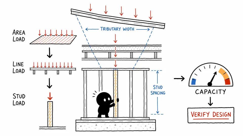
Convert roof and floor area loads into a wall line load using tributary width, then allocate that line load by stud spacing and compare it with an entered allowable capacity.
Combined area load—
Wall line load—
Load per stud—
Entered-capacity utilization—
Entered capacity reserve—
Planning screen—
LOAD-PATH SECTION
Follow load from tributary area to line and stud
The section keeps roof, floors, tributary width, spacing, and the user-supplied capacity visible. The capacity gauge is a screen, not a design seal.
| Stage | Input basis | Conversion | Result | Design question |
|---|
How to use
Trace entered roof and floor loads to one stud before comparing capacity
- Enter Roof dead load (psf), Roof live load (psf), Floor dead load per supported floor (psf).
- Confirm the remaining assumptions use the same project, measurement, or product basis.
- Read Combined area load together with Wall line load and Load per stud.
- Use load-path reconciliation to reconcile the result before exporting it.
- Confirm every load source and geometric basis, then send the demand path to the responsible structural professional before design use.
LOAD-PATH FUNDAMENTALS
Trace area load to wall line, tributary stud, and entered capacity
Required inputs
- Roof dead load (psf)
- Default: 15
- Roof live load (psf)
- Default: 20
- Floor dead load per supported floor (psf)
- Default: 10
- Floor live load per supported floor (psf)
- Default: 40
- Supported floors
- Default: 1
- Tributary width (ft)
- Default: 12
- Stud spacing (in o.c.)
- Default: 16
- Entered allowable stud capacity (lb)
- Default: 2500
Reported outputs
- Combined area load
- Wall line load
- Load per stud
- Entered-capacity utilization
- Entered capacity reserve
- Planning screen
CALCULATION METHOD
Preserve every load basis through the path
Combine compatible area loads, multiply by tributary width to obtain wall line load, then assign line load by stud spacing. Capacity utilization is reported only against the user-entered allowable value.
TRIBUTARY GEOMETRY
Load distributed over square area, such as psf.
Obtain unfactored or factored loads consistently from the project design basis.
LOAD TRANSFER
Load distributed along wall length, such as plf.
Add roof dead and live loads for the entered roof tributary area.
ENGINEERING BOUNDARY
Width of supported area assigned to the wall.
Multiply floor load by the number of supported floors only when the same tributary basis applies.
Detailed calculation process
Load-path reconciliation
qarea = qroof,dead + qroof,live + nfloors(qfloor,dead + qfloor,live)wline = qarea × tributary widthPstud = wline × spacing/12utilization = Pstud / entered capacity
Area, line, and stud loads retain full precision through utilization; formatting cannot be used to make an entered capacity comparison appear acceptable.
| Input | Default substitution | Requirement |
|---|---|---|
| Roof dead load (psf) | 15 | Required; use one consistent unit and basis |
| Roof live load (psf) | 20 | Required; use one consistent unit and basis |
| Floor dead load per supported floor (psf) | 10 | Required; use one consistent unit and basis |
| Floor live load per supported floor (psf) | 40 | Required; use one consistent unit and basis |
| Supported floors | 1 | Required; use one consistent unit and basis |
| Tributary width (ft) | 12 | Required; use one consistent unit and basis |
| Stud spacing (in o.c.) | 16 | Required; use one consistent unit and basis |
| Entered allowable stud capacity (lb) | 2500 | Required; use one consistent unit and basis |
- Convert area load to wall line load with tributary width.
- Allocate line load to a stud using on-center spacing.
- Compare the axial planning load with a capacity taken from a compatible design check.
- Stop at screening: verify load combinations, eccentricity, stability, openings, connections, and code separately.
Current load-path reconciliation will preserve the area, line, stud, and entered-capacity bases without treating the result as member approval.
Result interpretation
Use the load path to screen demand, not approve a wall
Utilization below one only means the simplified axial planning load is below the entered capacity. The result can still be unsafe if the capacity does not match species, grade, length, bracing, moisture, load duration, eccentricity, fire treatment, or the governing design method.
Visual interpretation
Follow load from tributary area to line and stud
The section keeps roof, floors, tributary width, spacing, and the user-supplied capacity visible. The capacity gauge is a screen, not a design seal. Read the graphic with the exact ledger: geometry and color show relationships, while the table remains the numerical record.
EVIDENCE FOR THIS MODEL
Document load source, tributary geometry, and capacity basis
Retain code edition, load source, load combination, dead/live/snow classification, tributary geometry, supported levels, spacing, stud species and grade, size, unbraced length, bracing, sheathing, openings, bearing, eccentricity, connection path, capacity-table source, adjustment factors, and engineer review.
SCOPE AND LIMITATIONS
Why this load-path screen is not member design
- Not structural design and not a substitute for sealed calculations.
- The model uses uniform gravity area loads and centered axial allocation.
- Wind, seismic, point loads, snow drift, uplift, bending, buckling interaction, openings, headers, connections, and foundation checks are excluded.
- Never enter a raw tabular capacity without verifying all adjustment factors and applicability.
KEY TERMINOLOGY
Area-to-stud load terminology
- Area load
- Load distributed over square area, such as psf.
- Line load
- Load distributed along wall length, such as plf.
- Tributary width
- Width of supported area assigned to the wall.
- Stud load
- Simplified share assigned by spacing.
- Allowable capacity
- Capacity from a compatible design method and conditions.
- Utilization
- Demand divided by entered capacity.
PRACTICAL DECISIONS
Spacing sensitivity versus Tributary-width error
Spacing sensitivity
Reducing spacing lowers the per-stud share but increases stud count. Structural adequacy still depends on wall height, bracing, species, grade, and load combination.
Tributary-width error
A small width mistake multiplies directly into line and stud load. Sketch the actual load path before trusting the input.
AUTHORITATIVE BASIS
References for area-to-stud load path
Important note
Not structural design and not a substitute for sealed calculations. Preserve the entered assumptions, exact ledger, and named source before using combined area load in a decision.
Frequently asked questions
Does utilization under 100% mean safe?
No. It passes only this simplified screen against the entered capacity.
Can I use factored loads?
Only with a capacity and design method on the same basis.
Does the page include wall self-weight?
No. Add it to dead load where required.
What about openings?
Headers, jacks, kings, concentrated reactions, and cripple studs require separate design.
Can I use snow as roof live load?
Enter the governing project load consistently; drift and combinations still need design review.
Does sheathing increase capacity?
Bracing conditions affect design, but this page does not calculate that increase.
Why show a planning margin at 80%?
It is a visual screen only, not a code-prescribed acceptance boundary.
Who must verify the result?
A qualified professional responsible for the project design.