Uniform horizontal water line
A straight, regularly supported run can use the line-load record for coordination before qualified hardware and structure checks.
Home & Construction
Expose the mass basis for a straight filled pipe run without inventing allowable hanger, rod, anchor, structure, seismic, thermal, or thrust capacity.
FILLED-PIPE DEAD LOAD
Annular pipe geometry and contained-fluid geometry are converted to weight before a planning factor and hanger spacing are applied. No support capacity is inferred.
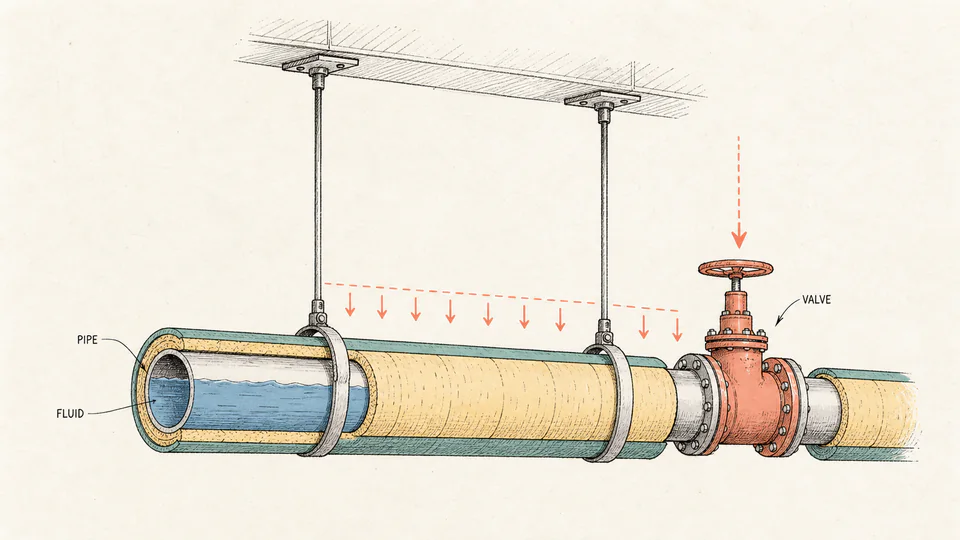
SUBJECT DECISION ILLUSTRATION
The illustration explains the professional setting without pretending to be a data chart. The ledger below preserves the entered values and calculation path.
| Load component | Geometry / quantity | Density / factor | Component load | Line or support result | Boundary |
|---|
How to use
Load fundamentals
Calculation method
Pipe-wall and fluid areas use circular geometry after inches are converted to feet. Each area is multiplied by run length and its entered density. Insulation and distributed accessories are added before line load is calculated. The planning factor applies to demand only and is not a code safety factor.
Geometry boundary
Schedule, SDR, wall type, material, and manufacturer determine actual outside and inside diameters. Small diameter errors affect both pipe material and contained-fluid volume.
Support boundary
End conditions, unequal spans, fittings, valves, vertical risers, anchors, branches, point loads, thermal forces, and support stiffness redistribute reactions. Use the average only for reconciliation.
Dynamic and code boundary
Water hammer, pressure thrust, earthquake restraint, vibration isolation, expansion, contraction, guide forces, anchor loads, corrosion, and fire conditions require separate models and governing support rules.
Detailed calculation process
The current result cards and component ledger provide the numerical reconciliation.
Result interpretation
Use service and planning line loads to communicate the represented distributed demand. Do not compare them with an allowable unless the hanger, rod, anchor, attachment, supporting member, load combination, and governing standard are all defined.
Decision analysis
Heavy valves, strainers, pumps, meters, branches, risers, offsets, and anchors should be modeled at their actual locations. Treating them as uniform weight can understate a local support reaction.
Evidence and data lineage
Keep pipe manufacturer and product, nominal size, schedule or dimension ratio, actual diameters, density, fluid and operating condition, insulation system, valve and fitting schedule, route and elevation, support spacing and details, point loads, planning-factor rationale, governing code, engineer, revision, and unrounded output.
Limits and exclusions
Key terminology
Worked decision cases
A straight, regularly supported run can use the line-load record for coordination before qualified hardware and structure checks.
Concentrated valve weight, vertical load, anchor action, and thermal forces invalidate a uniform average-hanger interpretation.
Authoritative basis
This is a dead-load planning record, not support design. Qualified professionals must establish the real load combinations, spacing, restraints, attachments, structure, safety factors, and code compliance.
Contained-fluid weight depends on bore area, which nominal size does not uniquely define.
No. It is an entered planning multiplier and does not replace governing load combinations or resistance factors.
A straight run divided into spans normally has one more support location than spans.
Only for a preliminary aggregate record; actual support design should preserve its location.
No. Spacing is an input that must already be justified by the applicable system and design.
Vertical risers require separate support, anchor, guide, branch, and thermal analysis.