Live calculation visualCurrent entered assumptions
Home & Construction
Roof Shingle Load Calculator
Keep load bases distinct while screening a simply supported rafter line and preserving the point-load position.
SIMPLIFIED RAFTER LOAD PATH
Keep roof-surface dead load and horizontal snow load on the correct bases
Designers and estimators can screen one simply supported rafter line using entered loads and tributary spacing. The page reconciles uniform and point loads to eave and ridge reactions; it never declares structural adequacy.
Larger bearing reaction—
Total vertical load—
Uniform rafter line load—
Eave reaction—
Ridge reaction—
Rafter slope length—
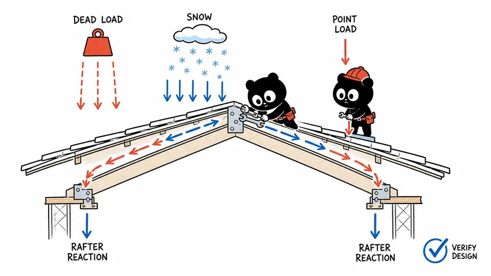
LOAD-PATH FREE BODY
Follow distributed bases and point position to each support
The roof free-body draws uniform load across horizontal run, places the point load at its entered coordinate, and scales two reaction arrows that must sum to total vertical load.
| Component | Area-load basis | Line load | Total load | Support effect |
|---|
How to use
Keep roof-surface dead load and horizontal snow load on the correct bases
- Obtain governing load values and combinations from the project design.
- Enter horizontal run and rise-per-12 without substituting sloped length.
- Enter on-center spacing to define tributary width for one rafter line.
- Keep permanent roof-cover dead load on sloped surface basis and snow/live load on the entered horizontal basis.
- Place the maintenance point load by horizontal distance from the eave.
- Review reaction reconciliation, then perform the required member, bearing, connection, uplift, and code checks elsewhere.
RAFTER LOAD-PATH FUNDAMENTALS
Distinguish horizontal projection, roof surface, tributary width, and reactions
- Horizontal projection
- Plan area used by many snow and roof-live load definitions.
- Roof surface
- Actual sloped area carrying roofing dead weight.
- Tributary width
- Spacing of roof area assigned to one repeated rafter.
- Line load
- Vertical force per horizontal foot along the simplified rafter model.
- Reaction
- Support force required for static vertical equilibrium.
CALCULATION METHOD
Place every load on its declared geometric basis
Convert roof-surface dead load and horizontal snow or live load to one rafter line, add the point load at its entered position, and solve the two vertical reactions by equilibrium.
LOAD BASIS
Load basis controls the answer
Multiplying a horizontal snow value by roof slope would double-convert its basis. Confirm how every project load is defined before entry.
REACTION DISTRIBUTION
Point location moves reactions
A point near the eave increases the eave reaction while total load stays fixed. Concentrated equipment and drift require project-specific models beyond this screen.
ENGINEERING BOUNDARY
Demand is not capacity
Reactions are loads, not permitted values. Rafter bending, shear, deflection, bearing, connections, species, grade, bracing, duration factors, and combinations still govern design.
Detailed calculation process
Rafter load and reaction reconciliation
The pitch factor converts only roof-surface dead load to force per horizontal foot. Horizontal snow/live load is not multiplied by pitch factor. Both receive rafter tributary width, then the point-load position allocates unequal support reactions.
pitch factor = √(1+(rise/12)²)w = spacing/12 × (dead psf×pitch factor + snow/live psf)W = wL + PReave = wL/2 + P(L−a)/L; Rridge = wL/2 + Pa/L
| Symbol | Meaning | Unit |
|---|---|---|
| L | Horizontal rafter run | ft |
| a | Point-load distance from eave | ft |
| w | Uniform vertical line load | lb/ft |
| P | Entered point load | lb |
| R | Bearing reaction | lb |
| spacing | Rafter tributary width | in |
- Pitch factor: √(1+(6/12)²) = 1.1180.
- Dead line load: 12×1.1180×2 = 26.833 lb/ft.
- Snow/live line load: 30×2 = 60.000 lb/ft.
- Uniform total: 86.833×12 = 1,041.996 lb; add 240 lb point load.
- Eave reaction = 700.998 lb; ridge reaction = 580.998 lb.
- Reaction sum 1,281.996 lb equals entered vertical-load total; reconciliation error is zero.
The live result cards and exact ledger above provide the final reconciliation for the current inputs.
Result interpretation
Use reactions and equilibrium as planning outputs only
The larger reaction identifies the more heavily loaded support in this single vertical case. Near-zero reconciliation error confirms equilibrium arithmetic only. It does not validate load values, member stiffness, code combinations, lateral stability, or uplift resistance.
Visual interpretation
Follow distributed bases and point position to each support
Arrow length shows relative load and reaction magnitude, not deformation. Changing point position redistributes reactions without changing total force; changing pitch affects the roof-surface dead component only. The sketch is not to scale for structural geometry.
EVIDENCE FOR THIS MODEL
Preserve load sources, bases, span geometry, and point position
Retain code edition, occupancy, risk category, ground and roof snow study, dead-load takeoff, roof geometry, spacing, point-load source and coordinate, load combination, member/support configuration, drift and sliding-snow review, wind uplift, and engineer approval.
SCOPE AND LIMITATIONS
Why equilibrium is not a roof design certificate
- Simply supported vertical static model only.
- No overhang, continuity, collar ties, thrust, drift, unbalanced snow, ponding, wind, seismic, or uplift.
- The rectangular tributary model does not resolve hips, valleys, dormers, or concentrated framing.
- No material or connection capacity is calculated.
KEY TERMINOLOGY
Rafter load-path and reaction terms
- Dead load
- Permanent weight of roofing and supported construction.
- Snow/live load
- Variable vertical load entered on its declared basis.
- Pitch factor
- Sloped-length divided by horizontal run.
- Tributary width
- Repeated spacing assigned to one member.
- Free body
- Isolated load-and-reaction model.
- Static equilibrium
- Force balance used for the reaction check.
PRACTICAL DECISIONS
Point load near eave versus Snow-drift roof
Point load near eave
Use the support split to locate the larger reaction, then design the actual rafter, seat, wall, and connection.
Snow-drift roof
Do not replace a drift distribution with one uniform psf input; use the governing engineered load diagram.
AUTHORITATIVE BASIS
References for simplified rafter load path
Important note
Do not purchase members, approve framing, or certify code compliance from this result. A qualified structural professional must establish loads, combinations, capacities, and details.
Frequently asked questions
Why is only dead load multiplied by pitch factor?
This model treats dead load as roof-surface psf and snow/live as horizontal-projection psf.
Does a zero reconciliation error prove the roof is safe?
No. It proves only that the simplified reactions sum to the modeled vertical load.
Can I enter ground snow load directly?
Not unless the governing procedure says it equals the project roof load; normally conversion and modifiers are required.
What if the point load is at the ridge?
Enter the horizontal run; the entire point-load share moves to the ridge reaction in this simple model.
Does rafter spacing affect total roof load?
It changes the load assigned to one rafter line, not the full roof.
Can this size rafters?
No. It supplies a planning load path, not a code design.