EN

Engineering

Bearing Capacity Calculator

Size a rolling bearing basic dynamic load rating from equivalent radial and axial load, speed, target hours, reliability factor, and bearing life exponent.

ROLLING BEARING RATING LIFE

Translate duty history into a required dynamic load rating

This calculator helps machine designers and maintenance engineers screen a candidate rolling bearing against a required adjusted operating life. It forms the equivalent dynamic load from entered X and Y factors, converts operating hours to revolutions, and applies the ISO 281 basic rating-life relation. The result is only valid when the catalog factors, lubrication regime, internal clearance, mounting, and load spectrum match the selected bearing.

Required dynamic rating C
Equivalent dynamic load P
Candidate adjusted life
Rating margin
Candidate basic life (million rev)
Selection screen

ROLLING BEARING RATING LIFE

Dynamic rating and life reconciliation

Compare the required C with the candidate catalog rating, then read the reconstructed candidate life. A positive rating margin is not permission to ignore minimum load, static safety, speed, fits, or lubrication.

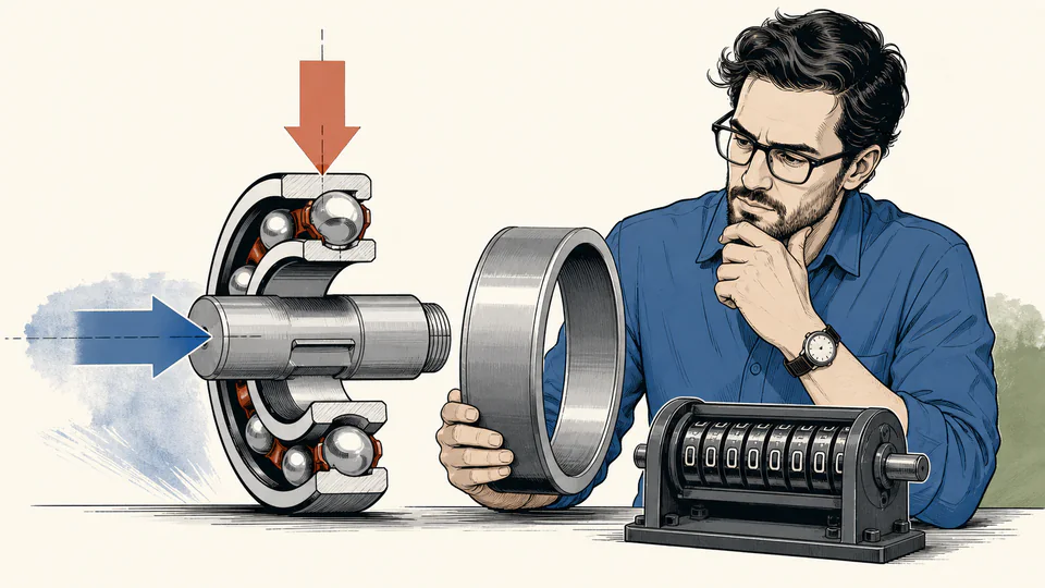
Editorial cutaway of a loaded bearing carrying radial and axial arrows while an engineer compares a catalog rating ring with a life counter
The illustration separates applied bearing reactions, catalog load factors, and the rating-life decision rather than implying that outside diameter alone defines capacity.
Dynamic rating and life reconciliationUnrounded calculation path
Live calculation ledger based on current inputs
Calculation stageInput AInput BCalculated valueBasis / unit

CURRENT CALCULATION PROCESS

Formula, substitution, intermediate values, and reconciliation

P = f_s(XF_r + YF_a); L_10 = 60nh/(10^6 a_1); C_required = P × L_10^(1/p)

The ISO 281 basic rating relation is inverted to solve for required basic dynamic rating. Entered catalog X and Y factors first combine radial and axial duty into P; target adjusted hours are then converted back to the basic L10 revolution basis using a1. The calculation deliberately leaves contamination, viscosity, fatigue load limit, and system reliability outside this screen.

Current default register: labels, meanings, units, and entered values
Input / symbolEngineering meaning and unitCurrent value
radialLoadNSteady radial load (N) — Use the bearing reaction at the governing duty point.8000
axialLoadNSteady axial load (N) — Preserve the sign convention used to select the catalog factors.1800
radialFactorCatalog radial factor X — Enter the X factor for this bearing and load ratio.1
axialFactorCatalog axial factor Y — Enter the Y factor from the same catalog row as X.1.6
serviceFactorApplication service factor — Represents agreed shock or duty severity, not an automatic safety factor.1.25
speedRpmRotational speed (rpm) — Use the sustained equivalent speed for the target life.1450
lifeHoursRequired adjusted life (h) — State whether this is operating time or calendar time.30000
reliabilityFactorReliability life factor a1 (%) — ISO life factor entered as a percentage; 100% represents the basic L10 basis.62
lifeExponentLife exponent p — Typically 3 for ball bearings and 10/3 for roller bearings.3
candidateRatingNCandidate basic dynamic rating C (N) — Use the catalog basic dynamic load rating, not static rating C0.62000

    Intermediate values remain unrounded until display formatting.

    HOW TO USE THIS MODEL

    Build the rating-life screen from a defensible duty point

    1. Derive radial and axial bearing reactions from the shaft free-body diagram at the load case that governs fatigue, including belt pull, gear thrust, overhung weight, and process force.
    2. Select X and Y from the candidate bearing manufacturer’s table using the correct contact angle, Fa/Fr ratio, and limiting e value; do not borrow factors from another bearing family.
    3. Apply only a documented service factor for shock or duty variation, then enter sustained speed and actual operating hours rather than calendar availability.
    4. Choose p for the rolling-element type and enter the reliability factor on the same statistical basis as the required life statement.
    5. Compare required C with the catalog candidate, then separately verify static capacity, minimum load, reference speed, lubrication, fits, clearance, and shaft/housing rigidity.

    ROLLING BEARING RATING LIFE FUNDAMENTALS

    What the rating-life equation does—and does not—represent

    Equivalent dynamic load
    A constant hypothetical radial load that would produce the same basic rating life as the entered combined radial and axial duty under the selected X and Y factors.
    Basic dynamic rating C
    The catalog load rating used in the ISO fatigue-life relation. It is not the maximum permissible instantaneous load and must not be confused with static rating C0.
    Basic rating life L10
    The life associated with 90% survival for a sufficiently large population of apparently identical bearings under stated conventional conditions.
    Life exponent p
    The exponent that makes predicted life highly sensitive to the C/P ratio: commonly 3 for ball bearings and 10/3 for roller bearings.
    Reliability factor a1
    A multiplier connecting basic L10 life to a different required reliability basis. It changes the statistical life target, not the physical load.
    Service factor
    An explicit duty multiplier used when the reaction calculation does not already resolve impact or variation. Double counting shock in both loads and factor overstates demand.

    MODEL AND FORMULA

    Invert the ISO 281 relation without hiding the life basis

    P = f_s(XF_r + YF_a); L_10 = 60nh/(10^6 a_1); C_required = P × L_10^(1/p)

    The ISO 281 basic rating relation is inverted to solve for required basic dynamic rating. Entered catalog X and Y factors first combine radial and axial duty into P; target adjusted hours are then converted back to the basic L10 revolution basis using a1. The calculation deliberately leaves contamination, viscosity, fatigue load limit, and system reliability outside this screen.

    DEEPER ENGINEERING ANALYSIS

    Selection issues that can overturn a favorable C margin

    Variable duty needs damage accumulation

    A single factored load is a screen. When speed and load vary by cycle, use a duty-spectrum equivalent load with the applicable life exponent and time or revolution fractions; a short high-load event can dominate fatigue damage.

    Modified life is more than reliability

    ISO modified rating life may include lubrication viscosity ratio, contamination, and fatigue load limit through an additional life modification factor. Those terms require bearing-specific data and cannot be inferred from C alone.

    System reliability differs from bearing reliability

    A machine with several critical bearings has a lower system survival probability than each bearing considered alone. Allocate reliability at the system level before choosing a1 for a single location.

    WORKED DECISION CASES

    Two decisions that use the result differently

    Continuous pump retrofit

    A pump speed increase raises target revolutions even when hydraulic reaction stays constant. The required C can increase enough to eliminate a familiar bearing that previously met the same calendar service interval.

    Intermittent indexing table

    The table has low annual hours but sharp acceleration loads. Use the resolved duty spectrum and confirm static safety; increasing a generic service factor alone can obscure which event controls fatigue versus permanent deformation.

    TECHNICAL LANGUAGE

    Bearing rating vocabulary used in the model

    Bearing reaction
    Radial or axial force transferred from the shaft into one bearing location.
    C/P ratio
    Dynamic rating divided by equivalent load; its exponent drives the basic life estimate.
    Contact angle
    Geometry that governs how a bearing shares radial and axial load and therefore which X/Y factors apply.
    Fatigue load limit
    Bearing-specific load used in modified-life methods; not included in this basic screen.
    Internal clearance
    Relative ring movement before mounting and thermal effects; incorrect clearance changes load distribution and heat.
    Static rating C0
    Catalog rating used for permanent-deformation checks, separate from the dynamic rating used here.

    EVIDENCE AND DATA LINEAGE

    Evidence to retain with a bearing selection record

    Keep the shaft reaction calculation and load cases, manufacturer catalog edition, bearing designation and internal design, X/Y/e factor table, C and C0 ratings, speed basis, duty-cycle hours, reliability allocation, lubricant and viscosity calculation, contamination assumption, fit and clearance selection, and the unrounded calculator output. If the catalog revises internal geometry or ratings, repeat the screen rather than carrying forward only the part number.

    LIMITS AND EXCLUSIONS

    Boundaries of the basic rating calculation

    • The model assumes a constant-equivalent load and speed; it does not accumulate damage across a duty spectrum.
    • It applies a1 only and omits ISO life modification for lubrication, contamination, and fatigue load limit.
    • It does not check static rating C0, minimum load, reference speed, cage limits, fits, clearance, misalignment, or thermal balance.
    • The X and Y factors are entered evidence. Incorrect catalog factors make the result dimensionally neat but physically wrong.
    • Basic rating life is a statistical population measure and cannot predict the exact failure hour of an individual bearing.

    RELIABLE SOURCES

    References for this page’s method and boundaries

    FREQUENTLY ASKED QUESTIONS

    Questions engineers ask before accepting the rating

    Can I enter the peak shaft load as P?

    Only when that peak is a defensible constant-equivalent fatigue duty. A variable load history should be condensed by the correct damage-weighted relation, not by selecting the largest event without its duration.

    Why can predicted life change dramatically with a small load change?

    The life relation raises C/P to p. Because p is near 3, even a modest increase in P can cause a much larger percentage reduction in calculated life.

    Should reliability factor be entered as 90?

    No automatic mapping is assumed. Enter the a1 multiplier stated by the governing ISO/manufacturer table as a percentage; the default 62% represents a multiplier of 0.62, not 62% survival.

    Does a positive rating margin prove the bearing is safe?

    No. The screen does not check static load, minimum load, speed, lubrication, thermal clearance, fits, misalignment, contamination, or shaft and housing deformation.

    Can I use p = 3 for every bearing?

    No. Ball and roller bearings use different exponents in the basic relation, and specialized bearings may require manufacturer methods.

    Why does the calculator ask for a candidate rating after calculating a required rating?

    The candidate value enables an independent reverse calculation of adjusted life. That reconciliation exposes a mistaken unit, factor, or catalog value before selection.

    IMPORTANT ENGINEERING NOTE

    Use the result as a documented rating screen, not a final bearing approval

    Bearing selection can affect rotating-equipment safety and availability. A qualified designer must confirm the complete load spectrum, shaft and housing system, static safety, lubricant, contamination, speed, temperature, fits, clearance, sealing, installation, and applicable manufacturer instructions before releasing a design.

    RELATED CALCULATORS

    Continue the engineering decision

    Use a separate model for the next boundary instead of folding it into this result.