Neutral and harmonic loading
Nonlinear loads can increase neutral and conductor heating even when phase currents appear balanced; the entered grouping factor is not a harmonic study.
Engineering
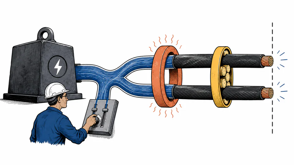
Translate real load demand into line current, current per parallel run, derated cable ampacity, utilization, and spare continuous-current capacity.
CIRCUIT LOADING
This calculator is for electrical designers and facility engineers who need to test whether a proposed conductor set can carry a stated load. It converts delivered real power to apparent input power, resolves single- or three-phase line current, distributes that current across parallel runs, and applies entered ambient and grouping factors. It is a screening calculation: the entered tabulated ampacity and correction factors must come from the governing wiring method and jurisdiction.
CIRCUIT LOADING
Use the utilization result to identify whether the proposed conductor set has enough continuous-current capacity under the entered installation factors. A pass on ampacity does not prove acceptable voltage drop, short-circuit withstand, protective-device coordination, neutral loading, or termination temperature.
| Load step | Power or installation basis | Electrical factor | Current basis | Calculated outcome |
|---|
CURRENT CALCULATION PROCESS
S = Pout / (PF × ηload); I = 1000S / (kphase × V); Iz = Itable × Camb × Cgroup × nruns; utilization = I / Iz
The method first works backward from delivered power through load efficiency and power factor. It then applies the correct phase multiplier to find line current and separately derates the selected conductor ampacity before comparing current with capacity.
Intermediate values remain unrounded until display formatting.
HOW TO USE THIS MODEL
CIRCUIT LOADING FUNDAMENTALS
MODEL AND FORMULA
The method first works backward from delivered power through load efficiency and power factor. It then applies the correct phase multiplier to find line current and separately derates the selected conductor ampacity before comparing current with capacity.
SYMBOLS AND DEFAULT CASE
| Symbol or input | Meaning | Unit or default |
|---|---|---|
| Pout | Delivered real load demand | kW |
| PF | Operating power factor | dimensionless |
| eta_load | Load conversion efficiency | dimensionless |
| k_phase | Phase multiplier: 1 or sqrt(3) | dimensionless |
| V | Circuit line voltage | V |
| I_z | Installed corrected ampacity | A |
| phases | Circuit phases (1 or 3) | 3 |
| voltageV | Line voltage (V) | 400 |
| realPowerKw | Delivered real load (kW) | 120 |
| powerFactorPercent | Power factor (%) | 88 |
| loadEfficiencyPercent | Load efficiency (%) | 94 |
| parallelRuns | Parallel cable runs | 2 |
| conductorAmpacityA | Tabulated ampacity per run (A) | 230 |
| ambientFactorPercent | Ambient correction factor (%) | 91 |
| groupingFactorPercent | Grouping correction factor (%) | 80 |
Percent inputs are converted to decimal factors once. The live calculation process above substitutes the current values in order, names intermediate quantities, reports the final result, and closes with a reverse or conservation check.
DEEP ENGINEERING ANALYSIS
Nonlinear loads can increase neutral and conductor heating even when phase currents appear balanced; the entered grouping factor is not a harmonic study.
A conductor can carry normal current yet fail short-circuit thermal withstand or be poorly coordinated with the upstream protective device.
Ampacity and voltage drop are separate constraints. Long circuits may require a larger conductor even when utilization is modest.
WORKED DECISION CASES
A plant uses coincident motor demand, measured power factor, motor efficiency, and the actual tray grouping arrangement. Two parallel runs meet ampacity, after which the engineer checks starting voltage and protection.
Connected nameplate totals overstate simultaneous demand, but a single optimistic diversity number would understate current. The designer records the adopted demand basis and verifies termination temperature ratings.
TECHNICAL GLOSSARY
EVIDENCE AND DATA LINEAGE
Keep the load list revision, coincidence assumptions, measured or manufacturer power factor and efficiency, system voltage basis, conductor construction, wiring method, insulation and termination temperatures, ambient record, grouping geometry, applicable ampacity table, correction-factor references, parallel-run details, and unrounded calculation output.
LIMITS AND EXCLUSIONS
RELIABLE SOURCES
FREQUENTLY ASKED QUESTIONS
The source must supply more apparent power for the same real power, so current increases at a fixed voltage.
If the entered kW is useful output, electrical input must cover the load conversion loss. Enter input kW directly only with 100% for this field.
You can if it is documented and mathematically equivalent, but separate factors make the installation basis easier to audit.
The arithmetic assumes matched runs. Real designs require equal conductor size, material, length, routing, and sound terminations.
No. Spare current is a planning margin within the entered steady-state model, not permission to exceed code or equipment ratings.
No. Protective-device rating, trip curve, fault current, coordination, and conductor protection are separate checks.
IMPORTANT ENGINEERING NOTE
Final cable selection must be reviewed by a qualified electrical professional using the adopted code, verified system and load data, equipment terminal ratings, protection study, voltage-drop and fault-duty checks, installation constraints, and manufacturer instructions.