Order effect
Sequential reductions compound; independent additive losses would answer a different model.
Engineering
Apply splice, corrosion, and buckling reserve deductions sequentially to a gross column capacity.
COLUMN CAPACITY LOSS
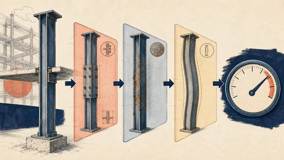
Sequential reductions are not the same as subtracting three percentages from the original capacity. This ledger shows the base, each deduction, and the remaining design capacity beside demand.
Decision boundary:For engineers reconciling declared splice, corrosion, and buckling deductions against axial demand; the inputs must already come from an approved resistance basis.
DECISION MAP
If the margin is negative, do not hide it by changing the order of deductions; revisit the evidence or redesign the member.
| Layer | Starting capacity (kN) | Reduction (%) | Loss or comparison (kN) | Meaning |
|---|
LIVE CALCULATION PROCESS
R_net = R_g(1-l_s)(1-l_c)(1-l_b); U = P / R_net x 100%
Each percentage reduces the capacity remaining after the previous layer. Display rounding occurs only after the net value and margin are calculated.
| Symbol | Meaning | Unit | Current input |
|---|---|---|---|
| Rg | Gross axial resistance | kN | 1200 |
| ls | Splice reduction applied to the current remainder | % | 4 |
| lc | Corrosion reduction applied after the splice step | % | 6 |
| lb | Buckling reserve deduction applied last | % | 8 |
| P | Current factored axial demand | kN | 950 |
HOW TO USE
SUBJECT FUNDAMENTALS
CALCULATION METHOD
Each percentage reduces the capacity remaining after the previous layer. Display rounding occurs only after the net value and margin are calculated.
DEEPER ANALYSIS
Sequential reductions compound; independent additive losses would answer a different model.
Each percentage needs a drawing, inspection, or calculation source.
A buckling reserve is not a substitute for a full stability analysis.
WORKED DECISION CASES
Starting from 1,200 kN, sequential 4%, 6%, and 8% reductions leave 996.2496 kN. A 950 kN design load uses 95.36% of net capacity and leaves a positive 46.2496 kN margin.
If a 900 kN gross resistance is reduced by 5%, 20%, and 10%, net capacity becomes 615.6 kN. A 700 kN demand exceeds it by 84.4 kN, so the negative margin remains visible rather than being clipped.
EVIDENCE AND DATA LINEAGE
Retain inspection reports, splice details, stability calculations, and load combination IDs.
LIMITS AND EXCLUSIONS
RELIABLE SOURCES
FREQUENTLY ASKED QUESTIONS
The model assumes each deduction applies to the remaining capacity.
Yes; zero means no deduction is entered for that layer.
Only if the entered reductions and base resistance come from the governing design method.
Treat it as a review signal; do not silently clip it to zero.
No, it is axial capacity only.
No; align the base resistance and demand definitions first.
IMPORTANT NOTE
Not a substitute for a signed structural capacity assessment.
RELATED CALCULATORS