EN

Engineering

Column Sensitivity Calculator

Stress-test a column safety factor under paired load and capacity changes.

COLUMN SENSITIVITY

Expose the corner case that governs a column check

A base safety factor can look comfortable until load rises while capacity falls. Compare the reference and adverse corners with the same units and assumptions.

Decision boundary:For structural engineers screening how paired demand and resistance assumptions change an axial ratio; code stability and interaction checks remain outside the model.

Base safety factor-
Minimum scenario factor-
Maximum scenario factor-
Scenario spread-
Governing corner-
Threshold status-

DECISION MAP

Column Sensitivity Calculator evidence path

Use the minimum scenario factor to decide whether the design needs better load data, reserve, or a formal redesign.
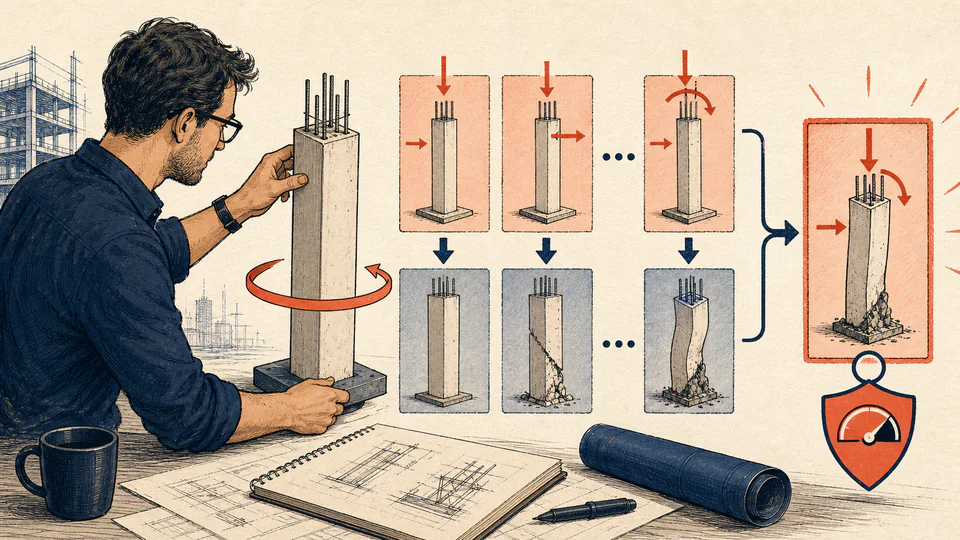
A structural engineer rotates a column model through paired load and capacity corners while the governing safety-factor marker remains in view.
Column Sensitivity Calculator calculation ledgerUnrounded path and interpretation
CaseAxial load (kN)Axial capacity (kN)Safety factorThreshold decision

LIVE CALCULATION PROCESS

Formula, symbols, substitution, and final check

FS = R / P; adverse FS = R(1-d_R) / [P(1+d_P)]

The corner cases are deterministic sensitivity checks. They do not replace a code load combination or a nonlinear interaction analysis.

SymbolMeaningUnitCurrent input
PBase axial demandkN420
RBase axial resistancekN980
dPPaired load-change magnitude%12
dRPaired capacity-change magnitude%10
FSreqProject review thresholddimensionless1.5

    HOW TO USE

    Expose the corner case that governs a column check

    1. Enter the baseline axial load and capacity using the same factored or allowable convention.
    2. Choose paired load-increase and capacity-reduction percentages from the uncertainty note.
    3. Enter the project review threshold rather than assuming a universal safety factor.
    4. Compare the base, favorable, and adverse corners to see which assumption drives the margin.
    5. Retain the governing case and then verify eccentricity, slenderness, and boundary conditions in the design model.

    SUBJECT FUNDAMENTALS

    Terms behind Column Sensitivity Calculator

    Axial load
    Factored compression demand
    Capacity
    Factored resistance
    Safety factor
    Capacity divided by load
    Corner case
    Paired adverse assumption
    Spread
    Max minus min factor

    CALCULATION METHOD

    Why this formula fits the topic

    FS = R / P; adverse FS = R(1-d_R) / [P(1+d_P)]

    The corner cases are deterministic sensitivity checks. They do not replace a code load combination or a nonlinear interaction analysis.

    DEEPER ANALYSIS

    Where professional judgement still matters

    Load path

    Confirm the load includes tributary floors, combinations, and eccentricity effects.

    Resistance reduction

    Capacity changes can represent degradation, slenderness, or material uncertainty.

    Code gate

    A sensitivity result is a screen; the governing standard still controls acceptance.

    WORKED DECISION CASES

    Two realistic uses

    Design review with paired uncertainty

    A 420 kN base load and 980 kN capacity give FS = 2.333. With load +12% and capacity -10%, the adverse factor is 882/470.4 = 1.875, still above the entered 1.5 review threshold.

    Existing member with little reserve

    A 600 kN load and 900 kN capacity start at FS = 1.5. Pairing a 20% load increase with a 25% capacity reduction produces 675/720 = 0.9375, directing the engineer to verify both demand and degradation assumptions.

    Technical glossary

    Euler load
    The reference elastic buckling load for the selected effective length.
    Imperfection factor
    A declared reduction for initial crookedness or eccentricity.
    Stiffness factor
    The retained stiffness share used in the sensitivity case.
    Load factor
    The adverse axial-demand multiplier.
    Utilization
    Factored demand divided by the adjusted capacity.
    Governing case
    The baseline or adverse row with the highest utilization.

    EVIDENCE AND DATA LINEAGE

    What to retain with the result

    Retain load combinations, resistance basis, material records, and sensitivity rationale.

    LIMITS AND EXCLUSIONS

    What this model does not establish

    • No buckling interaction, eccentricity, second-order effects, or code combination is solved.
    • Inputs must use a consistent force unit.
    • Do not use this screen as a stamped design check.

    RELIABLE SOURCES

    References for method and context

    FREQUENTLY ASKED QUESTIONS

    Column Sensitivity Calculator questions

    Are these code load combinations?

    No. They are explicit what-if corners around the entered base case.

    What if capacity change exceeds 100%?

    The page bounds the change at 100% so capacity cannot become negative.

    Why use a ratio?

    A ratio makes the demand-to-resistance margin comparable across cases.

    Does eccentricity matter?

    Yes, but it is outside this axial-only screen.

    Should I round before comparing?

    No; compare unrounded factors.

    Who accepts the design?

    The licensed design engineer and governing standard.

    IMPORTANT NOTE

    Before relying on the exported result

    Preliminary engineering screen only; obtain a code-compliant design review.

    RELATED CALCULATORS

    Continue the decision with a neighboring check