CS

Engineering

Conveyor Safety Factor Calculator

Screen a conveyor belt’s retained full-width tensile strength against peak operating tension, splice efficiency, condition retention, and an entered minimum factor.

BELT STRENGTH AND TENSION SCREEN

Test retained belt strength against the governing peak tension

This calculator is for conveyor designers, reliability engineers, and maintenance teams who already have a defensible peak belt-tension case and belt construction data. It converts rated strength per unit width into full-width strength, applies separate splice and condition-retention factors, and compares the retained strength with the strength demanded by an entered minimum tensile factor. It does not assess guarding, emergency stops, entanglement, fire, structural support, or personnel risk, so its result must never be described as a complete conveyor safety approval.

Actual retained-strength factor
Allowable peak at entered criterion (kN)
Peak-tension margin (kN)
Retained-strength margin
Criterion strength utilization
Tensile criterion screen

CALCULATION DETAIL

Retained belt-strength reconciliation

Review the current inputs, unrounded intermediate values, and final decision in the table below.

Retained belt-strength reconciliationUnrounded current-value analysis
Retained belt-strength reconciliation based on current inputs
Strength checkpointEntered basisTransformationCurrent valueUnit

HOW TO USE THIS MODEL

Build a traceable tensile-strength screen

  1. Identify the exact installed belt construction, finished width, rated longitudinal strength, cover designation, and splice type from controlled procurement and commissioning records.
  2. Use a tension study that includes the governing steady, acceleration, loaded-start, stopping, braking, take-up, and credible upset cases; enter the largest applicable belt tension rather than drive power.
  3. Enter splice efficiency from a qualified joint design, test, or manufacturer procedure and keep it separate from any field-condition reduction supported by inspection or remaining-life evidence.
  4. Enter the minimum tensile factor required by the governing project specification or manufacturer for the stated belt and operating case; record whether the criterion changes for transient tension.
  5. Read actual factor, allowable peak, and margin together, then complete independent checks for pulley and transition stresses, take-up travel, local damage, structural loads, fire, guarding, and controls.

BELT STRENGTH AND TENSION SCREEN FUNDAMENTALS

The strength quantities that must not be mixed

Rated strength per width
The declared longitudinal belt rating in N/mm. It becomes a full-width force only after multiplication by the actual belt width.
Full-width breaking strength
A nominal tensile force derived from belt width and rating. It is not an allowable working tension until the chosen design criterion and reductions are applied.
Splice efficiency
The fraction of belt strength retained by the installed joint system. Mechanical fasteners and vulcanized splices require different evidence and failure considerations.
Condition retention
A separate engineering reduction for deterioration, damage, environmental exposure, or known defects. It should come from inspection and assessment, not a convenient default.
Peak operating tension
The largest belt tension in the defined load case. Start-up, braking, jam release, and take-up dynamics may govern even when steady running tension is lower.
Tensile safety factor
Retained tensile strength divided by governing peak tension. It is a component-strength ratio and must not be confused with a machinery risk-reduction rating.

MODEL AND FORMULA

Retain every reduction before comparing demand

S_ret = b × R × η_splice × η_condition; SF_actual = S_ret ÷ T_peak; T_allow = S_ret ÷ SF_required

Rated belt strength R is expressed per millimetre of belt width, so multiplying it by finished width b yields nominal full-width breaking strength. Splice efficiency and condition retention are applied as distinct decimal multipliers because joint quality and remaining belt condition represent different evidence. The current factor divides retained full-width strength by governing peak tension; the allowable peak reverses the same equation at the entered minimum factor. All intermediate calculations remain in newtons or kilonewtons and are rounded only for display.

DEEPER SUBJECT ANALYSIS

Engineering judgments hidden behind a single factor

The splice can govern before the carcass

A belt rating describes the belt construction, but the installed joint interrupts or transfers that reinforcement. Joint type, step geometry, materials, curing, fastener pattern, workmanship, and cyclic damage can reduce retained capacity differently. Using a generic percentage without joint evidence can overstate the available strength even when the arithmetic is correct.

Peak tension must come from the right event

The governing tensile demand may occur during a loaded start, emergency stop, regenerative descent, blocked chute, take-up transient, or braking sequence. A steady-state pull copied from a motor calculation cannot represent those events. Freeze the mass distribution, acceleration law, control mode, friction assumptions, and take-up response used to define T_peak.

A tensile factor is not a safety-system score

This page cannot verify nip-point guards, pull cords, isolation, access, belt drift switches, braking redundancy, structural stability, dust, fire, or inspection practice. Those hazards follow machinery-safety and site procedures. A high tensile factor can coexist with an unacceptable personnel or process risk.

CURRENT CALCULATION PROCESS

Formula, symbols, substitution, intermediate values, and reconciliation

S_ret = b × R × η_splice × η_condition; SF_actual = S_ret ÷ T_peak; T_allow = S_ret ÷ SF_required

Rated belt strength R is expressed per millimetre of belt width, so multiplying it by finished width b yields nominal full-width breaking strength. Splice efficiency and condition retention are applied as distinct decimal multipliers because joint quality and remaining belt condition represent different evidence. The current factor divides retained full-width strength by governing peak tension; the allowable peak reverses the same equation at the entered minimum factor. All intermediate calculations remain in newtons or kilonewtons and are rounded only for display.

Current symbol register: entered values, meanings, and units
Input / symbolMeaning, basis, and unitCurrent value
widthMmBelt width (mm) — Use the actual finished belt width, not conveyor frame width.1000
beltStrengthNmmRated belt strength (N/mm) — Take the declared longitudinal full-thickness rating from the belt specification.800
spliceEfficiencyPercentSplice efficiency retained (%) — Use qualified joint data for the installed splice type and workmanship.85
conditionRetentionPercentCondition retention (%) — Document the evidence for age, damage, environment, and inspection derating.90
peakTensionKnGoverning peak operating tension (kN) — Use the maximum dynamic tension from the stated operating, start, stop, or braking case.75
requiredSafetyFactorRequired minimum tensile factor — Enter the project, manufacturer, or governing specification criterion; the calculator does not choose it.8

    Intermediate values remain unrounded until display formatting.

    EVIDENCE AND DATA LINEAGE

    Records required before the ratio can support a decision

    Retain the belt certificate and revision, width measurement, construction and cover designation, splice design and installer record, joint test or qualification basis, inspection history, damage map, operating temperature and environment, complete tension-model load cases, drive and brake control sequence, take-up data, required factor source, unrounded calculation record, and engineering approval. The belt rating, splice efficiency, condition retention, peak tension, and required criterion must refer to the same physical belt and operating state.

    FIELD CONTEXT

    See the decision boundary in its real operating setting

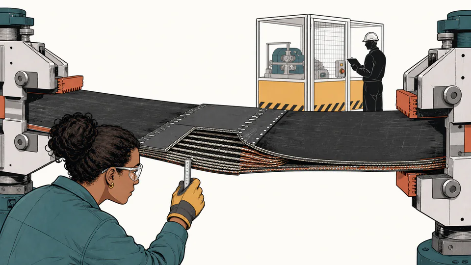
    Editorial cutaway of a conveyor belt splice being pulled between two test grips while an engineer checks a retained-strength tag and a separate guarding checklist stays closed
    The field illustration separates the tensile calculation from the wider machinery-safety decision: one verifies retained belt strength, while the other requires a full hazard assessment.

    LIMITS AND EXCLUSIONS

    What this tensile screen does not establish

    • It does not calculate belt tension from conveyor geometry, material loading, acceleration, brakes, drives, or take-up dynamics; T_peak is an entered engineering result.
    • It does not select a minimum factor or splice efficiency. Those values must come from the applicable specification, manufacturer, design authority, or qualified test.
    • It treats splice and condition retention as independent multipliers and does not model fatigue, local stress concentration, impact, bending, transition, or pulley contact effects.
    • It is not applicable to machinery guarding, personnel exposure, emergency controls, structural supports, fire performance, or functional safety.
    • A measured or suspected defect can invalidate a uniform condition-retention factor and require local assessment, testing, repair, or replacement.

    TECHNICAL LANGUAGE

    Conveyor-belt strength vocabulary

    Belt carcass
    The reinforcement structure that carries longitudinal tensile load beneath the covers.
    Mechanical fastening
    A joint made with installed metal or polymer fasteners; its static test basis differs from a vulcanized splice.
    Vulcanized splice
    A bonded joint built through prepared plies or cords and cured materials to transfer tensile load.
    Take-up
    The system that maintains and adjusts belt tension while accommodating stretch, loading, and movement.
    Transient tension
    A time-dependent tension excursion caused by acceleration, stopping, braking, or elastic wave propagation.
    Retained strength
    The nominal full-width strength after the explicitly entered splice and condition multipliers are applied.

    WORKED DECISION CASES

    Two applications with different governing evidence

    Uphill aggregate conveyor after a capacity increase

    Higher material loading and acceleration change peak belt tension, while the existing hot-vulcanized splice may retain its qualified efficiency. Recalculate T_peak for the new start sequence, then use this screen to determine whether the original belt class and splice still clear the project criterion.

    Aged overland belt with mechanical repair fasteners

    The nameplate belt rating may remain unchanged, but local carcass damage, repair geometry, and fastener condition can reduce retained strength. Enter only an evidence-backed splice and condition value; if those values are unknown, the correct output is not a guessed factor but a requirement for inspection or testing.

    RELIABLE SOURCES

    References for the model and its limits

    IMPORTANT NOTE

    Do not release a conveyor from this ratio alone

    Conveyor belt rupture and uncontrolled movement can cause severe injury, fire, equipment damage, and production loss. A qualified conveyor engineer must approve the tension cases, belt and splice specification, remaining condition, required design criterion, take-up and drive behavior, guarding, braking, emergency controls, inspection, and site-specific regulatory obligations.

    FREQUENTLY ASKED QUESTIONS

    Questions to settle before accepting the factor

    Is this a complete conveyor safety-factor calculation?

    No. It is a retained belt-tensile-strength screen. It does not evaluate guards, controls, structural safety, fire, access, brakes, or other hazards required for a conveyor safety assessment.

    Where should the required minimum factor come from?

    Use the governing project specification, belt manufacturer, splice design basis, or responsible engineering authority for the stated construction and load case. The calculator intentionally does not invent a universal factor.

    Can I enter motor torque converted to belt pull as peak tension?

    Only if a complete dynamic tension model shows that value is the governing belt tension at the evaluated location. Drive torque alone may omit take-up response, belt elasticity, braking, and tension-wave effects.

    Why are splice efficiency and condition retention separate?

    The splice changes how reinforcement is transferred across the joint, while condition retention represents deterioration or damage in the current belt. Combining them into one undocumented reduction hides which evidence controls the result.

    Does a negative tension margin mean the belt will fail immediately?

    No. It means the entered retained strength does not clear the entered design criterion. It is a blocking engineering finding, not a prediction of the exact failure time or mode.

    Can I use the belt manufacturer’s nominal rating for an old repaired belt?

    The nominal rating is only the starting point. Repairs, splice condition, carcass damage, heat, chemicals, and aging may require a lower evidence-backed retention value or direct specialist assessment.
    RELATED CALCULATORS

    Continue with a genuinely related decision