Material surcharge and flowability
Lump size, moisture, segregation, and surcharge angle affect stable loading and spill risk.
Engineering
Convert required bulk mass flow and density into loaded cross-section, belt speed, material line load, resistance, lift power, and drive power.
BULK BELT CONVEYOR DESIGN
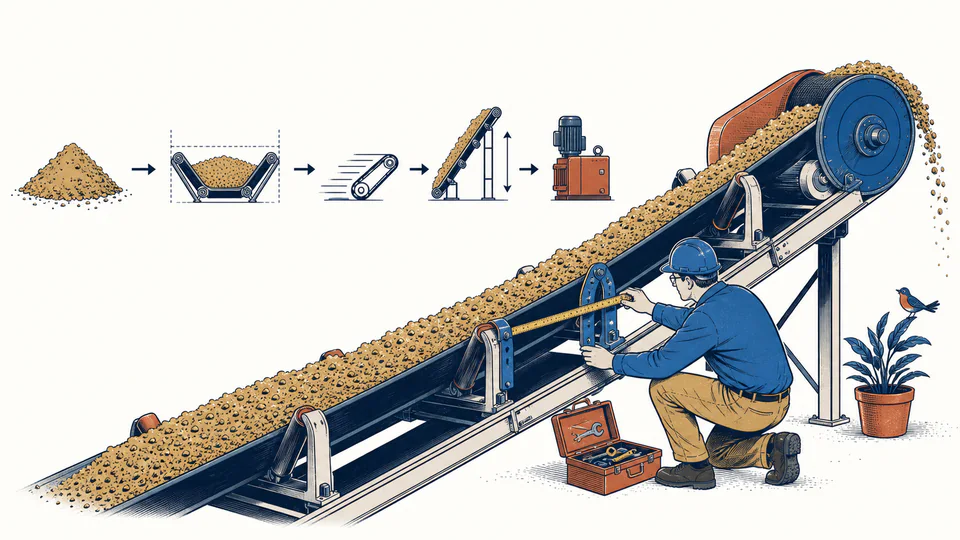
A bulk conveyor cannot be designed from tonnes per hour alone. This calculator converts mass flow to volume, creates a loaded cross-section from belt width and an entered area coefficient, solves the belt speed required for that area, and estimates lift and running-resistance power. Every coefficient remains visible so the result is a planning screen rather than a hidden CEMA or ISO design claim.
BULK BELT CONVEYOR DESIGN
Use the speed result to judge whether proposed width and loading geometry are plausible. If speed exceeds the entered limit, increase effective loaded area, revise throughput, or split duty; do not simply raise speed without reviewing material behavior, loading, dust, wear, tracking, and safety.
| Design step | Throughput or geometry | Coefficient or comparison | Calculated result | Meaning |
|---|
CURRENT CALCULATION PROCESS
Qv = mdot/rho; Aload = kA B^2; v = Qv/Aload; Pshaft = [mdot g H + fres (mdot/v) g L v]/etaDrive
The entered loaded-area coefficient represents material surcharge and usable loading geometry. Required speed follows from volume continuity; the power screen adds material lift and one explicit running-resistance term before drive efficiency.
| Input / symbol | Engineering meaning and unit | Current value |
|---|---|---|
| massFlowTph | Required mass flow (t/h) — Continuous design throughput | 650 |
| bulkDensityKgM3 | Bulk density (kg/m3) — Loose bulk density for conveyed condition | 1450 |
| beltWidthMm | Proposed belt width (mm) — Usable belt width basis | 1000 |
| areaCoefficient | Loaded-area coefficient — Cross-section area divided by belt width squared | 0.075 |
| maxBeltSpeed | Entered maximum belt speed (m/s) — Material and project criterion | 3.5 |
| conveyorLengthM | Conveyor length (m) — Modeled carrying path | 180 |
| liftM | Vertical lift (m) — Net discharge rise | 22 |
| resistanceCoefficient | Running resistance coefficient — Planning coefficient for moving material path | 0.035 |
| driveEfficiency | Drive efficiency (%) — Gearbox, coupling, and drive boundary | 92 |
Intermediate values remain unrounded until display formatting.
HOW TO USE THIS MODEL
BULK BELT CONVEYOR DESIGN FUNDAMENTALS
MODEL AND FORMULA
The entered loaded-area coefficient represents material surcharge and usable loading geometry. Required speed follows from volume continuity; the power screen adds material lift and one explicit running-resistance term before drive efficiency.
DEEPER ENGINEERING ANALYSIS
Lump size, moisture, segregation, and surcharge angle affect stable loading and spill risk.
Acceleration, impact, skirt friction, chute trajectory, and dust can govern belt speed and wear.
Steady running power does not establish start torque, brake duty, take-up travel, transient tensions, rollback prevention, or control sequence.
WORKED DECISION CASES
A wide belt at moderate speed limits impact and dust while carrying required mass; drive power is then checked using detailed CEMA or ISO resistance.
Low bulk density demands much more volume for the same mass. A larger cross-section rather than excessive speed improves containment and transfer behavior.
TECHNICAL LANGUAGE
EVIDENCE AND DATA LINEAGE
Keep material identification, lump size, moisture, bulk density test, surcharge and trough basis, belt width and edge clearance, throughput profile, route and lift survey, resistance coefficient source, drive efficiency, unrounded results, transfer-point assumptions, and the detailed conveyor design reference.
LIMITS AND EXCLUSIONS
RELIABLE SOURCES
FREQUENTLY ASKED QUESTIONS
No. It depends on trough, surcharge, edge clearance, material, and loading stability.
Volume occupancy depends on conveyed bulk condition, not solid-particle density.
The arithmetic can show it, but that signals the proposed width and loading basis do not satisfy the chosen criterion.
Only through the entered simplified resistance coefficient; final design needs the governing detailed resistance method.
No. Starting, service factor, gearbox, thermal duty, electrical supply, and transient requirements remain.
No. Trajectory, impact, wear, sealing, dust, plugging, and access need separate design.
RELATED CALCULATORS
Use these follow-on models to test a different boundary without hiding it inside this calculation.
IMPORTANT ENGINEERING NOTE
Final conveyor design requires verified bulk-material data, the governing CEMA or ISO method, full route and resistance model, dynamic and structural analysis, drive and brake selection, transfer design, guarding and hazard review, and qualified approval.