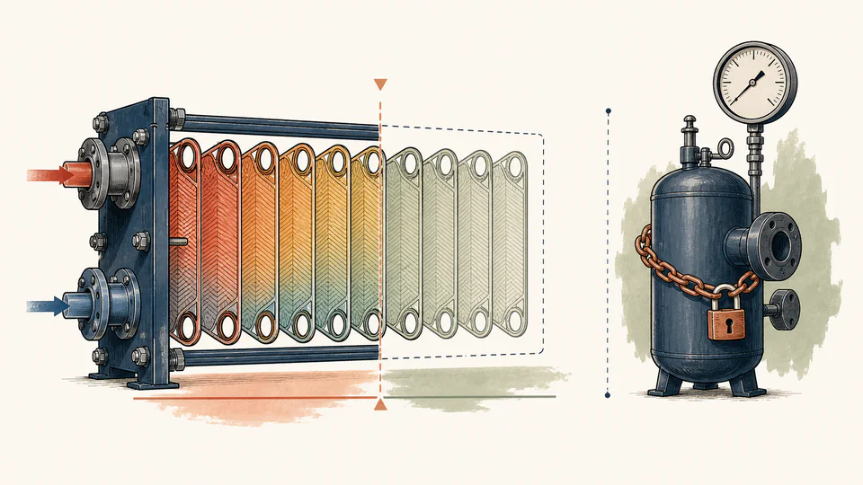
Margin basis must be singular
Design teams may add margin to duty, U, fouling resistance, area, and temperature program. Combining all without a ledger creates accidental compounding and an exchanger that is difficult to control.
Engineering
Compare fouling-derated UA-LMTD thermal capacity with required duty and an entered project margin, then solve the area needed to meet that thermal screen.
THERMAL DUTY MARGIN
This calculator screens whether entered heat-transfer area can provide a required duty after LMTD correction and a user-supplied fouling derate. It reports the ratio of available thermal capacity to process duty and compares it with an explicit project-required factor. The result is a thermal performance margin only; it says nothing about tubesheet, shell, nozzle, tube, gasket, relief, fatigue, or pressure-code safety.
THERMAL DUTY MARGIN
If the available-to-required factor is below the project criterion, revisit U, area, temperature program, fouling basis, or duty before release. Never interpret the thermal factor as an ASME pressure or material safety factor.
| Thermal margin stage | Input / capacity A | Factor / capacity B | Calculated value | Unit / basis |
|---|
CURRENT CALCULATION PROCESS
Q_available = U A (F)(LMTD)(f_foul)/1000; SF_thermal = Q_available/Q_required; A_required = SF_req Q_required×1000/(U F LMTD f_foul)
The corrected UA-LMTD capacity is reduced by the entered available-capacity fraction, then divided by the un-margined required process duty. A second comparison multiplies process duty by the required project factor, so the displayed kW and area margins show exactly what must be added or recovered.
| Input / symbol | Engineering meaning and unit | Current value |
|---|---|---|
| requiredDutyKw | Required process duty (kW) — Use the governing duty case before design margin. | 520 |
| overallU | Overall U (W/m²·K) — Use a documented clean or specified coefficient basis. | 680 |
| areaM2 | Installed heat-transfer area (m²) — Use effective area on the same basis as U. | 52 |
| lmtdC | Countercurrent LMTD (K) — Calculate from valid positive terminal differences. | 21 |
| correctionFactor | LMTD correction factor F (%) — Enter the arrangement-specific correction factor. | 92 |
| foulingDerate | Available capacity after fouling (%) — A project derate; 82% means 18% capacity reduction. | 82 |
| requiredSafetyFactor | Required thermal factor — Explicit project criterion, not a code pressure factor. | 1.12 |
Intermediate values remain unrounded until display formatting.
HOW TO USE THIS MODEL
THERMAL DUTY MARGIN FUNDAMENTALS
MODEL AND FORMULA
The corrected UA-LMTD capacity is reduced by the entered available-capacity fraction, then divided by the un-margined required process duty. A second comparison multiplies process duty by the required project factor, so the displayed kW and area margins show exactly what must be added or recovered.
DEEPER ENGINEERING ANALYSIS
Design teams may add margin to duty, U, fouling resistance, area, and temperature program. Combining all without a ledger creates accidental compounding and an exchanger that is difficult to control.
Oversurface can drive a cold outlet beyond a control target, increase condensate subcooling, alter two-phase behavior, or require bypass. Margin should be reviewed with the control philosophy.
F below the project’s accepted range can indicate a poor temperature program or arrangement. Adding area may not resolve pinch behavior, and a different pass arrangement may be preferable.
WORKED DECISION CASES
Required duty is fixed, but warm summer inlet water reduces LMTD. The area requirement rises; hiding this case inside an annual-average U would understate the seasonal constraint.
Measured clean U is strong, yet deposits reduce available conductance. A documented fouling derate shows whether cleaning frequency or spare area—not a larger pressure rating—is the relevant action.
TECHNICAL LANGUAGE
EVIDENCE AND DATA LINEAGE
Keep the governing duty case, stream properties and phase, temperature program, U derivation and area basis, clean/dirty definition, fouling resistance or derate source, correction-factor method, exchanger arrangement, installed effective area, required project factor, control philosophy, and independent mechanical design package. The margin ledger should show where each allowance enters once and only once.
LIMITS AND EXCLUSIONS
RELIABLE SOURCES
FREQUENTLY ASKED QUESTIONS
No. It is a project thermal-capacity ratio. Pressure containment, allowable stress, corrosion allowance, fatigue, tubesheet, gasket, and relief design require separate code calculations.
Only if the relationship is documented and not double counted. Usually choose one consistent clean-to-dirty treatment and preserve the resistance or test basis.
The raw factor shows capacity relative to process need; the margin comparison shows whether that factor meets the explicit project criterion.
Not automatically. More area can affect control, phase behavior, pressure drop, velocity, fouling distribution, and cost. Review the complete design.
Use a method applicable to the exchanger flow arrangement, such as verified charts, equations, or design software, with terminal temperatures that satisfy the method.
It can screen required area on the entered thermal basis. Final selection needs detailed thermal rating, pressure drop, mechanical design, materials, vibration, fouling, control, maintainability, and applicable codes.
IMPORTANT ENGINEERING NOTE
Have a qualified exchanger specialist confirm the thermal model and a qualified pressure-equipment engineer confirm the mechanical design, materials, corrosion, inspection, relief, and applicable codes. Do not label this calculated thermal ratio as a certified safety factor.
RELATED CALCULATORS
Use a separate model for the next boundary instead of folding it into this result.