Starting torque is a curve
A motor can have adequate running torque but fail to accelerate a high-inertia load. Compare motor and load torque across speed and integrate acceleration time.
Electrical Engineering
Compare required running torque with service-factor-adjusted, duty- and temperature-derated motor torque.
MOTOR TORQUE MARGIN
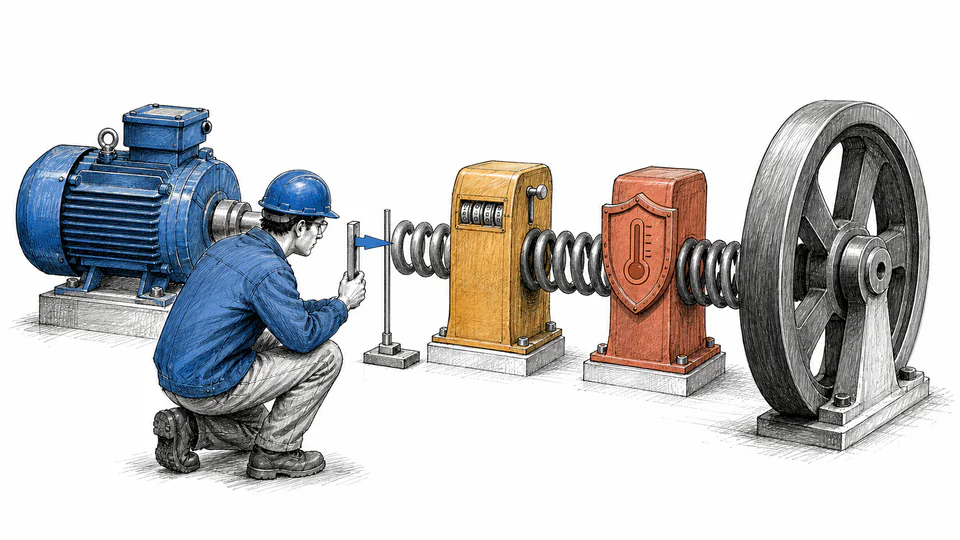
This screen converts rated shaft power and speed to torque, applies an entered service factor and explicit duty and temperature allowances, then compares available running torque with process demand. It keeps the owner-selected acceptance factor separate from the motor nameplate.
MOTOR TORQUE MARGIN
Use this as a running-torque planning screen. Starting, accelerating, pull-up, breakdown, reversing, and pulsating torque require speed-torque and thermal analysis.
| Torque branch | Input A | Input B | Factor | Result | Meaning |
|---|
CURRENT CALCULATION PROCESS
F_T = T_available/T_required; T_available = 9550(P_rated/n) × SF × (1 − d_duty − d_temp)
Rated mechanical power at loaded speed establishes nameplate torque. Service-factor allowance and declared deratings adjust that torque before comparison with required running torque.
| Symbol | Engineering meaning | Unit | Default |
|---|---|---|---|
| P_rated | Rated mechanical shaft output | kW | 30 |
| n_rated | Rated loaded speed | rpm | 1450 |
| SF | Nameplate service factor | ratio | 1.15 |
| d_duty | Duty-cycle allowance | % | 5 |
| d_temp | Temperature or installation allowance | % | 4 |
| T_required | Required running torque | N*m | 170 |
| F_required | Owner-selected torque criterion | ratio | 1.1 |
Intermediate values remain unrounded until display formatting.
HOW TO USE THIS MODEL
MOTOR TORQUE MARGIN FUNDAMENTALS
MODEL AND FORMULA
Rated mechanical power at loaded speed establishes nameplate torque. Service-factor allowance and declared deratings adjust that torque before comparison with required running torque.
DEEPER ENGINEERING ANALYSIS
A motor can have adequate running torque but fail to accelerate a high-inertia load. Compare motor and load torque across speed and integrate acceleration time.
Voltage and frequency tolerance, ambient, altitude, insulation, enclosure, and nameplate instructions constrain use of service factor. Persistent operation may reduce efficiency and life.
Compressors, crushers, and reciprocating machines impose peaks and torsional variation. An average torque margin can hide damaging peaks.
WORKED DECISION CASES
A conveyor process needs more running torque after throughput expansion. The screen tests adjusted motor torque, while a separate acceleration and gearbox rating check addresses transient and mechanical limits.
A nominally adequate motor operates in a hotter enclosure. Entered installation allowance shows whether the apparent nameplate margin survives the actual environment.
TECHNICAL LANGUAGE
EVIDENCE AND DATA LINEAGE
Retain motor nameplate, speed-torque curve, service-factor conditions, driven-equipment torque curve, gearbox data, duty cycle, starts per hour, inertia, ambient, altitude, voltage, process state, derating basis, protection, and the entered acceptance criterion.
LIMITS AND EXCLUSIONS
RELIABLE SOURCES
FREQUENTLY ASKED QUESTIONS
Only when manufacturer and applicable standards allow it under the actual conditions. Efficiency, temperature rise, and life may differ from rated operation.
Torque is derived from actual mechanical power and shaft speed. Synchronous speed would understate torque for an induction motor operating with slip.
No. Starting requires the motor torque-speed curve to exceed load torque plus acceleration demand through the full speed range.
If required torque is specified at the driven machine, reflect gearbox ratio and efficiency to obtain motor-shaft torque. Do not mix shaft boundaries.
Use peak, RMS, or cycle-specific methods appropriate to the mechanism and thermal duty. One steady value may be insufficient.
Not as one universal value for every application. Establish it from duty, uncertainty, criticality, transients, redundancy, and owner practice.
RELATED CALCULATORS
Use the next model to test a separate operating boundary without hiding it inside this result.
IMPORTANT ENGINEERING NOTE
Qualified engineering review should verify the motor and driven system across start, acceleration, steady load, upset, braking, thermal duty, environment, VFD operation, mechanical ratings, and protection before selection or load increase.