Current-limit ownership
A breaker frame, trip setting, cable ampacity, VFD current limit, and motor rated current are not interchangeable. Identify which boundary the entered amperes represents.
Electrical Engineering
Find usable continuous motor shaft capacity from the lower of derated nameplate output and available three-phase current capacity.
MOTOR CONTINUOUS CAPACITY
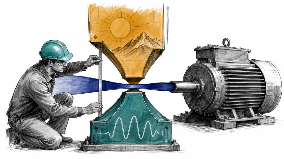
This calculator evaluates two independent steady-state ceilings: a nameplate shaft-output branch reduced by entered ambient and altitude allowances, and a line-current branch converted through power factor and efficiency. The lower branch defines usable output at the reviewed point.
MOTOR CONTINUOUS CAPACITY
The smaller branch is a screening bottleneck, not permission to load the motor. Verify rated current, service factor, VFD output, conductor and protection limits, cooling, duty, and driven-equipment torque.
| Capacity branch | Input A | Allowance/input B | Factor | Capacity | Meaning |
|---|
CURRENT CALCULATION PROCESS
P_usable = min[P_rated(1−d_ambient−d_altitude), √3VI_limitPFη/1000]
One branch derates mechanical nameplate output. The other converts available three-phase current into electrical input and then shaft output. Both use the same operating voltage, power-factor, efficiency, and speed basis.
| Symbol | Engineering meaning | Unit | Default |
|---|---|---|---|
| P_rated | Rated continuous shaft output | kW | 75 |
| V_LL | Available line voltage | V | 400 |
| I_limit | Available line-current ceiling | A | 120 |
| PF | Power factor at reviewed load | ratio | 0.87 |
| eta | Efficiency at reviewed load | ratio | 0.93 |
| d_ambient | Ambient derating allowance | % | 5 |
| d_altitude | Altitude derating allowance | % | 3 |
Intermediate values remain unrounded until display formatting.
HOW TO USE THIS MODEL
MOTOR CONTINUOUS CAPACITY FUNDAMENTALS
MODEL AND FORMULA
One branch derates mechanical nameplate output. The other converts available three-phase current into electrical input and then shaft output. Both use the same operating voltage, power-factor, efficiency, and speed basis.
DEEPER ENGINEERING ANALYSIS
A breaker frame, trip setting, cable ampacity, VFD current limit, and motor rated current are not interchangeable. Identify which boundary the entered amperes represents.
A self-cooled motor may lose continuous torque at low speed even when current is available. Use motor/VFD derating curves.
A motor with adequate running capacity may exceed voltage-drop, generator, VFD, or protection limits while accelerating.
WORKED DECISION CASES
A replacement process needs more shaft power, but the existing drive current limit produces a lower capacity than the derated motor nameplate. The drive is the first upgrade candidate.
A motor nameplate appears adequate at sea level. Entered altitude and ambient allowances show whether thermal capacity becomes lower than the available electrical branch.
TECHNICAL LANGUAGE
EVIDENCE AND DATA LINEAGE
Retain motor and VFD nameplates, continuous current-limit source, conductor and protection data, voltage and speed, power-factor and efficiency source, ambient, altitude, enclosure, cooling method, duty, torque curve, process requirement, and the identified limiting branch.
LIMITS AND EXCLUSIONS
RELIABLE SOURCES
FREQUENTLY ASKED QUESTIONS
The motor system cannot sustainably exceed either its thermal/nameplate output or the shaft power possible through the available current boundary.
Not automatically. Breaker rating or pickup may not equal motor continuous current capacity, conductor ampacity, or VFD output capability.
No. This page intentionally treats continuous derated nameplate output as the thermal branch. Apply service factor only under its stated conditions and a separate policy.
Cooling and drive capability can change. Use manufacturer constant-torque/constant-power curves and VFD limits rather than this single-point screen.
Power factor converts apparent electrical input to real input; efficiency converts real input to mechanical output. They describe different losses.
No. Starting requires torque-speed curves, inertia, acceleration time, voltage drop, current, duty, and protection analysis.
RELATED CALCULATORS
Use the next model to test a separate operating boundary without hiding it inside this result.
IMPORTANT ENGINEERING NOTE
Qualified engineering review should confirm every electrical, thermal, mechanical, control, environmental, starting, duty and protection boundary. Do not uprate a motor or feeder from the calculated lower branch alone.