Instrument placement matters
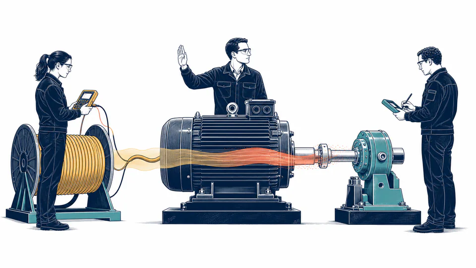
VFD input, VFD output, motor terminals, coupling, and driven-equipment shaft are different boundaries. State exactly where each measurement is taken.
Electrical Engineering
Calculate motor efficiency from synchronized three-phase electrical readings and measured shaft torque and speed.
MOTOR EFFICIENCY MEASUREMENT
This page compares measured three-phase real input with mechanical output derived from torque and speed. It is designed for a synchronized operating-point test, not for estimating efficiency from current or nameplate data alone.
MOTOR EFFICIENCY MEASUREMENT
A credible test requires synchronized, calibrated instruments and a stable process point. Use repeat tests and uncertainty to decide whether a small efficiency difference is meaningful.
| Balance item | Input A | Input B | Constant or factor | Calculated value | Unit |
|---|
CURRENT CALCULATION PROCESS
η = (Tn/9550)/(√3 V_LL I_L PF/1000) × 100%
Torque in N·m times speed in rpm divided by 9550 gives shaft kW. Three-phase voltage, current and true power factor give electrical kW. Their ratio is operating efficiency.
| Symbol | Engineering meaning | Unit | Default |
|---|---|---|---|
| V_LL | Measured line-to-line voltage | V | 460 |
| I_line | Measured line current | A | 40 |
| PF | True power factor | ratio | 0.88 |
| T_shaft | Measured shaft torque | N*m | 95 |
| n | Measured shaft speed | rpm | 1760 |
| P_in | Three-phase real electrical input | kW | derived |
| P_shaft | Torque-speed mechanical output | kW | derived |
Intermediate values remain unrounded until display formatting.
HOW TO USE THIS MODEL
MOTOR EFFICIENCY MEASUREMENT FUNDAMENTALS
MODEL AND FORMULA
Torque in N·m times speed in rpm divided by 9550 gives shaft kW. Three-phase voltage, current and true power factor give electrical kW. Their ratio is operating efficiency.
DEEPER ENGINEERING ANALYSIS
VFD input, VFD output, motor terminals, coupling, and driven-equipment shaft are different boundaries. State exactly where each measurement is taken.
When loss is only a few percent of input, modest power or torque error can dominate the inferred loss. Report instrument classes and repeatability.
Efficiency varies across load and speed. Build a curve only from multiple stable, synchronized operating points.
WORKED DECISION CASES
A rewound motor is tested at a controlled load. Direct input-output balance identifies whether measured performance matches the repair acceptance criterion.
A VFD-driven compressor is measured at several speed/load points. Each point uses the same boundary so the resulting efficiency map supports control optimization.
TECHNICAL LANGUAGE
EVIDENCE AND DATA LINEAGE
Retain raw analyzer channels, torque and speed time series, synchronization method, calibration certificates, sampling interval, motor and VFD identification, measurement boundaries, ambient and winding condition, process state, repeated runs, and unrounded calculations.
LIMITS AND EXCLUSIONS
RELIABLE SOURCES
FREQUENTLY ASKED QUESTIONS
A passive motor cannot continuously deliver more mechanical power than it receives electrically. The condition usually indicates mismatched timestamps, units, signs, or instruments.
No. PWM waveforms often require suitable bandwidth, sampling, and power-analysis methods. Follow analyzer and drive guidance.
Not for a measured efficiency test. It would derive output from the value being evaluated rather than independently measuring it.
Stable enough that synchronized averages represent the same state and repeated results fall within the intended uncertainty.
Most loss ultimately becomes heat, but cooling airflow, stored thermal energy, auxiliaries, and the chosen boundary affect a thermal comparison.
Only if boundaries, instruments, load, speed, voltage, temperature, and uncertainty are comparable. Standardized laboratory ratings may still be the better procurement basis.
RELATED CALCULATORS
Use the next model to test a separate operating boundary without hiding it inside this result.
IMPORTANT ENGINEERING NOTE
Contractual or regulatory efficiency should be established with the applicable standard test method, calibrated equipment, controlled conditions, uncertainty analysis, and qualified personnel. This field ratio is an operating-point calculation.