No-load subtraction is not full segregation
A no-load test includes friction, windage, core, and some stator copper effects at different current and slip. Direct subtraction cannot uniquely allocate loaded losses.
Electrical Engineering
Reconcile measured motor input and shaft output, estimate hot stator I-squared-R loss, and expose residual loss.
MOTOR LOSS RECONCILIATION
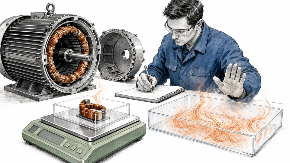
This field-oriented model compares measured three-phase input with measured torque-speed output, then estimates stator copper loss from per-phase hot resistance and connection. The remaining loss is deliberately labeled residual rather than falsely allocated among rotor, core, friction, windage, and stray components.
MOTOR LOSS RECONCILIATION
Use the residual as a diagnostic quantity, not a named failure mode. Separating rotor, core, mechanical, and stray losses requires a standard segregated-loss test or additional measurements.
| Power component | Measurement A | Measurement B | Multiplier/context | Calculated value | Unit or boundary |
|---|
CURRENT CALCULATION PROCESS
P_total loss = P_in − P_shaft; P_stator cu = 3I_phase²R_phase; P_residual = P_total loss − P_stator cu
Three-phase real input and torque-speed output establish measured total loss. Wye phase current equals line current; delta phase current equals line current divided by √3. Hot per-phase resistance gives a stator copper estimate; everything else remains residual.
| Symbol | Engineering meaning | Unit | Default |
|---|---|---|---|
| V_LL | Measured line-to-line voltage | V | 460 |
| I_line | Measured line current | A | 40 |
| PF | True power factor | ratio | 0.88 |
| T_shaft | Measured shaft torque | N*m | 90 |
| n | Measured shaft speed | rpm | 1760 |
| R_phase | Hot per-phase winding resistance | ohm | 0.12 |
| P_0 | Measured no-load input | kW | 1.2 |
Intermediate values remain unrounded until display formatting.
HOW TO USE THIS MODEL
MOTOR LOSS RECONCILIATION FUNDAMENTALS
MODEL AND FORMULA
Three-phase real input and torque-speed output establish measured total loss. Wye phase current equals line current; delta phase current equals line current divided by √3. Hot per-phase resistance gives a stator copper estimate; everything else remains residual.
DEEPER ENGINEERING ANALYSIS
A no-load test includes friction, windage, core, and some stator copper effects at different current and slip. Direct subtraction cannot uniquely allocate loaded losses.
Using line-to-line resistance as per-phase resistance or ignoring delta phase current can create a copper estimate larger than total measured loss.
Input power, torque, speed, resistance, temperature, and timing uncertainty can be comparable to a small residual. Repeat tests and quantify uncertainty before diagnosing degradation.
WORKED DECISION CASES
After a rewind, measured total loss increases. Hot-resistance I²R explains only part of the change, so the remaining residual directs a standardized test instead of an unsupported core-loss claim.
A motor shows elevated residual loss with stable copper estimate. Vibration, temperature, no-load test, lubrication, and airflow evidence are gathered before assigning mechanical loss.
TECHNICAL LANGUAGE
EVIDENCE AND DATA LINEAGE
Retain raw three-phase power channels, torque and speed series, motor and drive identification, connection diagram, hot-resistance measurement and temperature correction, no-load test conditions, calibration certificates, sample timing, ambient, load state, vibration and temperature observations, and unrounded balance values.
LIMITS AND EXCLUSIONS
RELIABLE SOURCES
FREQUENTLY ASKED QUESTIONS
Because it also contains rotor copper, mechanical, stray-load losses, and measurement uncertainty. Additional tests are needed to separate them.
No. Correct resistance to operating winding temperature or measure it appropriately after the run; cold resistance understates I²R loss.
For a balanced delta, phase current is line current divided by √3. The page converts line current before applying 3I²R.
It can be a comparison, but no-load conditions differ in current, slip, temperature, and airflow. It does not uniquely identify core and mechanical components.
That inconsistency points to wrong connection, resistance basis, temperature, current, timestamps, torque, speed, or instrument data. The calculator rejects a material mismatch.
Only with waveform-capable power measurement and a clearly defined boundary. PWM, harmonic losses, drive output methods, and low-speed cooling require special care.
RELATED CALCULATORS
Use the next model to test a separate operating boundary without hiding it inside this result.
IMPORTANT ENGINEERING NOTE
Use calibrated instruments, correct winding-resistance temperature, synchronized boundaries, uncertainty analysis, applicable standardized test methods, and qualified motor expertise before efficiency guarantees, repair acceptance, or fault diagnosis.