Low-flow requirements
A velocity ceiling does not cover solids transport, self-cleansing, mixing, or residence time.
Engineering
Solve maximum flow independently from velocity and pressure-drop limits, then report the lower governing pipe capacity and margins.
PIPE HYDRAULIC CAPACITY
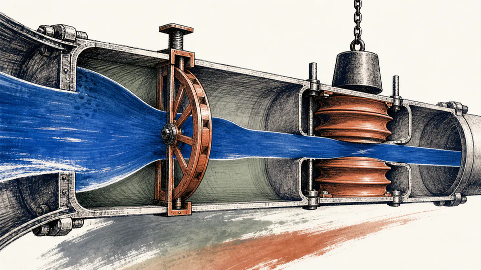
Pipe capacity has no universal value independent of acceptance criteria. This calculator determines one flow from an entered velocity ceiling and solves another from allowed pressure drop using Darcy-Weisbach plus fittings. The lower flow governs while both candidates and the hydraulic state remain visible.
PIPE HYDRAULIC CAPACITY
Use the governing criterion to assess more pressure, larger bore, shorter or cleaner path, or revised criteria. Confirm both limits before calling the minimum a design capacity.
| Capacity constraint | Entered limit | Geometry or comparison | Solved flow or value | Decision |
|---|
CURRENT CALCULATION PROCESS
Qvelocity=A vmax; solve Qpressure from DeltaPmax=rho g[f(L/D)+K]v(Q)^2/(2g); Qcapacity=min(Qvelocity,Qpressure)
Pressure-limited flow is solved iteratively because Reynolds number and friction factor vary with flow. Independent limits are converted to flow before taking the lower one.
| Input / symbol | Engineering meaning and unit | Current value |
|---|---|---|
| diameterMm | Internal diameter (mm) — Actual bore | 160 |
| lengthM | Pipe length (m) — Represented length | 350 |
| roughnessMm | Absolute roughness (mm) — Material and condition specific | 0.05 |
| density | Fluid density (kg/m3) — At operating condition | 998 |
| dynamicViscosityMpaS | Dynamic viscosity (mPa*s) — At operating condition | 1.002 |
| minorK | Combined minor-loss coefficient K — Same reference velocity | 10 |
| velocityLimit | Entered velocity limit (m/s) — Project or service criterion | 2.5 |
| pressureDropLimitKpa | Allowed pressure drop (kPa) — Allocated loss across this boundary | 85 |
Intermediate values remain unrounded until display formatting.
HOW TO USE THIS MODEL
PIPE HYDRAULIC CAPACITY FUNDAMENTALS
MODEL AND FORMULA
Pressure-limited flow is solved iteratively because Reynolds number and friction factor vary with flow. Independent limits are converted to flow before taking the lower one.
DEEPER ENGINEERING ANALYSIS
A velocity ceiling does not cover solids transport, self-cleansing, mixing, or residence time.
Rapid momentum change can create surge unrelated to steady loss.
Valves, meters, exchangers, filters, pumps, and downstream equipment may govern first.
WORKED DECISION CASES
Pressure allowance is consumed before the velocity ceiling, so a larger bore and pumping lifecycle are compared.
Velocity governs despite ample pressure because of noise and transient concerns.
TECHNICAL LANGUAGE
EVIDENCE AND DATA LINEAGE
Keep boundaries, actual bore, length, fittings, roughness, fluid condition, velocity criterion, pressure budget, other system requirements, solver state, Reynolds and friction factor, unrounded candidate flows, and approved criterion.
LIMITS AND EXCLUSIONS
RELIABLE SOURCES
FREQUENTLY ASKED QUESTIONS
No. Use service-specific criteria.
Different nonlinear constraints must each be solved into flow.
No. The entered allowance applies to this pipe boundary.
Only when pressure governs and all other limits permit it.
Capacity remains velocity-limited until the criterion is formally revised.
No. Wall, rating, degradation, supports, and code checks are separate.
RELATED CALCULATORS
Use these follow-on models to test a different boundary without hiding it inside this calculation.
IMPORTANT ENGINEERING NOTE
Adopted capacity requires complete hydraulic scenarios, equipment and control constraints, transient and integrity analysis, material and service limits, applicable codes, and qualified engineering approval.