Boundary manipulation
Calling all discharge head useful makes the ratio look perfect; useful service must reflect the process.
Engineering
Separate useful delivery head from pipe and fitting losses, calculate hydraulic delivery efficiency, and combine it with pump efficiency in a reconciled power balance.
PIPE DELIVERY EFFICIENCY
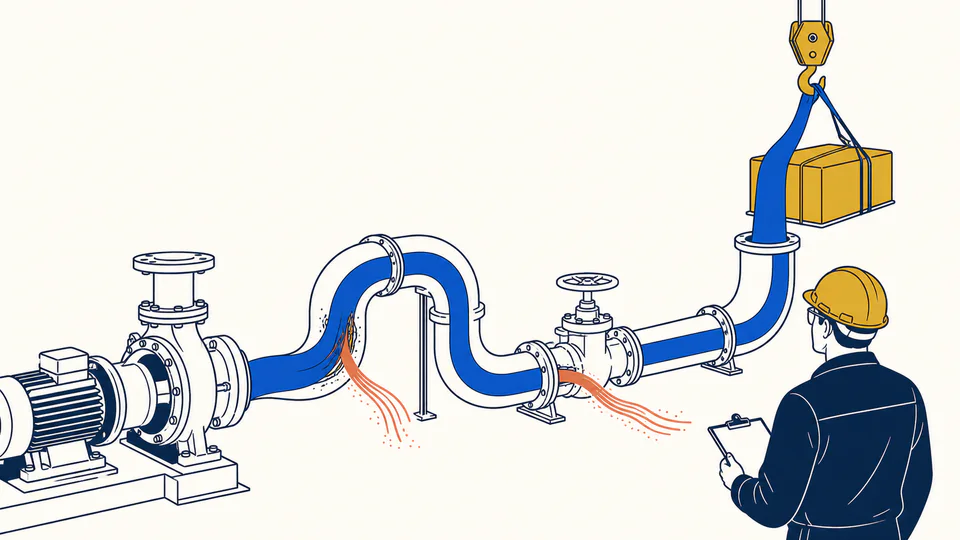
Pipe efficiency is meaningful only after the useful boundary is declared. This calculator treats delivery head as the useful hydraulic task, derives pipe and fitting losses at current flow, and compares useful head with total pump head. It combines that path efficiency with documented pump efficiency and reconciles useful power, shaft input, and modeled loss.
PIPE DELIVERY EFFICIENCY
Use the output to identify whether improvement should focus on diameter, roughness, fittings, or pump operation. Lower loss is beneficial only when equal useful flow and head are maintained.
| Power or head item | Primary input | Secondary input | Calculated result | Boundary meaning |
|---|
CURRENT CALCULATION PROCESS
etaPipe = Huseful/(Huseful + hmajor + hminor); etaCombined = etaPipe etaPump; Puseful = rho g Q Huseful
Pipe efficiency is a head ratio at one flow, not a universal property. Pump efficiency is applied to total head so useful power plus modeled loss reconciles with shaft input.
| Input / symbol | Engineering meaning and unit | Current value |
|---|---|---|
| flowM3h | Delivered flow (m3/h) — Actual flow at the assessed point | 110 |
| diameterMm | Internal diameter (mm) — Actual bore | 175 |
| lengthM | Straight pipe length (m) — Length on the same roughness basis | 420 |
| roughnessMm | Absolute roughness (mm) — Condition-specific value | 0.06 |
| density | Fluid density (kg/m3) — At operating condition | 997 |
| dynamicViscosityMpaS | Dynamic viscosity (mPa*s) — At operating condition | 0.89 |
| usefulHeadM | Useful delivery head (m) — Net service delivered at chosen boundary | 24 |
| minorK | Combined fittings coefficient K — Local losses on same velocity basis | 16 |
| pumpEfficiency | Pump efficiency at operating point (%) — Curve or test value at the same point | 80 |
Intermediate values remain unrounded until display formatting.
HOW TO USE THIS MODEL
PIPE DELIVERY EFFICIENCY FUNDAMENTALS
MODEL AND FORMULA
Pipe efficiency is a head ratio at one flow, not a universal property. Pump efficiency is applied to total head so useful power plus modeled loss reconciles with shaft input.
DEEPER ENGINEERING ANALYSIS
Calling all discharge head useful makes the ratio look perfect; useful service must reflect the process.
Friction changes strongly with flow, so one percentage cannot describe a duty profile.
A valve may dissipate head deliberately; improvements must preserve stable authority and safe operation.
WORKED DECISION CASES
A larger bore is compared at equal useful head and flow; reduced shaft input is checked against pump operation and lifecycle cost.
A variable-speed alternative is assessed against control stability and minimum flow instead of treating valve loss as automatically avoidable.
TECHNICAL LANGUAGE
EVIDENCE AND DATA LINEAGE
Keep boundary definitions, required delivery pressure or elevation, flow profile, actual bore, roughness, fittings and valves, fluid properties, pump curve or test point, control mode, unrounded balance, hours, and every changed assumption.
LIMITS AND EXCLUSIONS
RELIABLE SOURCES
FREQUENTLY ASKED QUESTIONS
Not when elevation gain is intended service; the boundary decides.
Loss depends on velocity, Reynolds number, and components while useful head may not scale.
No. Add motor and drive efficiencies for an electrical boundary.
Only if the proposed control method preserves stable and safe operation.
It cuts loss but may raise cost, residence time, fouling, or low-velocity risk.
Not as a simple efficiency gain; normalize the service or state the changed outcome.
RELATED CALCULATORS
Use these follow-on models to test a different boundary without hiding it inside this calculation.
IMPORTANT ENGINEERING NOTE
Evaluate changes across the real duty profile with verified measurements, pump and system curves, control requirements, minimum-flow and NPSH limits, lifecycle cost, and qualified engineering review.