Continuous restraint
Multi-span pipes redistribute reactions through stiffness, gaps, settlement, friction, guides, and anchors.
Engineering
Calculate pipe metal and contained-fluid mass per metre, operating and factored line load, simple-span support reaction, and screening bending moment.
PIPE GRAVITY LOAD
A support sees more than empty pipe mass. This calculator derives metal and fluid cross-sections from outside diameter and wall thickness, adds insulation and cladding, applies an entered dynamic factor, and produces a simple-span reaction and moment screen. It makes gravity input auditable while leaving thermal, occasional, concentrated, and code stress analysis to the governing model.
PIPE GRAVITY LOAD
Use the ledger to verify support-load inputs and compare operating, empty, or test cases. Transfer governing distributed and concentrated loads into a proper piping and support model.
| Load component | Geometry or mass basis | Density or span | Calculated value | Unit or meaning |
|---|
CURRENT CALCULATION PROCESS
Apipe = pi(OD^2-ID^2)/4; mline = Apipe rhoPipe + Afluid rhoFluid + minsulation; wdesign = mline g F; Mmax = wdesign L^2/8
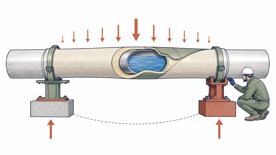
The line is a uniformly loaded simply supported span. Two equal end reactions and a midspan moment reconcile distributed gravity load; the model does not calculate pipe stress, local stress, or multi-span continuity.
| Input / symbol | Engineering meaning and unit | Current value |
|---|---|---|
| outsideDiameterMm | Pipe outside diameter (mm) — Actual specified OD | 219.1 |
| wallThicknessMm | Nominal wall thickness (mm) — Wall used for weight in the named case | 8.18 |
| pipeDensity | Pipe material density (kg/m3) — Material-specific density | 7850 |
| fluidDensity | Operating fluid density (kg/m3) — Use zero for an empty case | 998 |
| insulationMass | Insulation and cladding mass (kg/m) — Include tracing or jacket if appropriate | 12.5 |
| supportSpan | Screening support span (m) — Simple equal-span approximation only | 5.5 |
| dynamicFactor | Entered dynamic load factor — Project-specific and at least 1.0 | 1.15 |
Intermediate values remain unrounded until display formatting.
HOW TO USE THIS MODEL
PIPE GRAVITY LOAD FUNDAMENTALS
MODEL AND FORMULA
The line is a uniformly loaded simply supported span. Two equal end reactions and a midspan moment reconcile distributed gravity load; the model does not calculate pipe stress, local stress, or multi-span continuity.
DEEPER ENGINEERING ANALYSIS
Multi-span pipes redistribute reactions through stiffness, gaps, settlement, friction, guides, and anchors.
Expansion, wind, seismic, relief thrust, water hammer, slugging, and vibration can govern.
Reduced wall changes mass and stress; hydrotest fluid and temporary items can exceed operating weight.
WORKED DECISION CASES
Steel and insulation set the gravity baseline while thermal expansion and anchor forces remain in the flexibility model.
Water fill, blinds, and hoses create a temporary case that may govern support reactions.
TECHNICAL LANGUAGE
EVIDENCE AND DATA LINEAGE
Keep pipe specification, geometry source, material and corrosion condition, fluid or test density, insulation and tracing takeoff, support locations and types, concentrated items, dynamic basis, combinations, model revision, units, unrounded mass ledger, and final support-analysis reference.
LIMITS AND EXCLUSIONS
RELIABLE SOURCES
FREQUENTLY ASKED QUESTIONS
Schedule is a designation; calculation needs actual geometry.
Only if the named load case assumes corroded wall; load and stress cases may use different assumptions.
Normally represent it as a concentrated load at its position.
Amplification depends on event and response; the default is illustrative.
No. Deflection, stress, local effects, thermal movement, vibration, and code limits remain.
Mass remains useful, but reactions and bending need a geometry-specific model.
RELATED CALCULATORS
Use these follow-on models to test a different boundary without hiding it inside this calculation.
IMPORTANT ENGINEERING NOTE
Final support design requires applicable piping and structural codes, complete load cases, a restraint and flexibility model, local and global capacity checks, constructability review, and competent engineering approval.