Code details
Applicable equations may include diameter conventions, Y coefficient, temperature, quality, and component rules.
Engineering
Calculate net wall after mill tolerance and corrosion allowance, thin-wall hoop stress, effective allowable, screening pressure capacity, utilization, and comparison factor.
PIPE PRESSURE MARGIN SCREEN
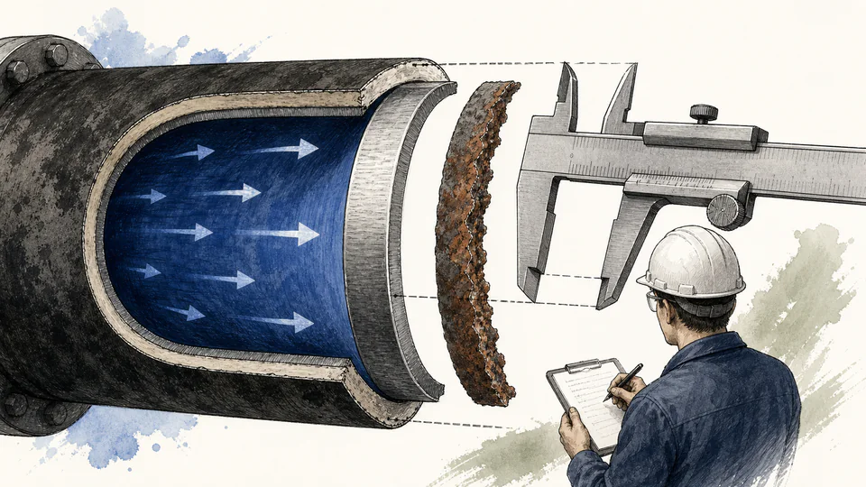
Nominal thickness is not the wall available for every pressure comparison. This calculator subtracts entered mill tolerance and corrosion allowance, calculates a thin-wall hoop-stress screen, applies a weld factor to allowable stress, and reports pressure margin and utilization. It is transparent and deliberately not a governing piping-code equation.
PIPE PRESSURE MARGIN SCREEN
Use this as an arithmetic and data-basis check. Positive margin does not close omitted code, fabrication, degradation, and loading requirements.
| Pressure screen step | Numerator or nominal | Deduction or denominator | Calculated result | Meaning |
|---|
CURRENT CALCULATION PROCESS
tnet = tnom(1 - mill tolerance) - corrosion allowance; sigmah = P Do/(2 tnet); Pscreen = 2 S E tnet/Do; factor = Pscreen/P
A simple membrane hoop relation uses outside diameter and remaining wall. Deductions and joint factor are visible, while code-specific coefficients, component rules, external pressure, and load combinations remain outside.
| Input / symbol | Engineering meaning and unit | Current value |
|---|---|---|
| outsideDiameterMm | Pipe outside diameter (mm) — Actual specified OD | 273 |
| nominalThicknessMm | Nominal wall thickness (mm) — Before deductions | 9.27 |
| corrosionAllowanceMm | Corrosion allowance (mm) — Reserved service loss | 1.5 |
| millTolerancePercent | Negative mill tolerance (%) — Applicable product specification | 12.5 |
| designPressureMpa | Design pressure (MPa) — Governing internal design pressure | 2.4 |
| allowableStressMpa | Allowable stress (MPa) — Code/material value at design temperature | 138 |
| weldFactor | Weld quality factor (%) — Effective joint factor for this screen | 100 |
| requiredFactor | Required comparison factor — Project screen, not automatically a code factor | 1.5 |
Intermediate values remain unrounded until display formatting.
HOW TO USE THIS MODEL
PIPE PRESSURE MARGIN SCREEN FUNDAMENTALS
MODEL AND FORMULA
A simple membrane hoop relation uses outside diameter and remaining wall. Deductions and joint factor are visible, while code-specific coefficients, component rules, external pressure, and load combinations remain outside.
DEEPER ENGINEERING ANALYSIS
Applicable equations may include diameter conventions, Y coefficient, temperature, quality, and component rules.
Pitting, grooves, cracks, erosion, and weld interaction are not uniform allowance.
Weight, displacement, wind, seismic, vibration, and cycling can govern.
WORKED DECISION CASES
A reviewer reproduces deductions and approximate hoop stress before auditing the supplier code calculation.
Measured general wall is screened before local thinning, uncertainty, remaining life, and fitness-for-service assessment.
TECHNICAL LANGUAGE
EVIDENCE AND DATA LINEAGE
Keep code edition, line and material specification, OD and wall source, tolerance clause, corrosion basis, pressure and temperature, allowable table entry, joint-factor basis, fabrication and examination, inspection data, unrounded calculation, and approved final design.
LIMITS AND EXCLUSIONS
RELIABLE SOURCES
FREQUENTLY ASKED QUESTIONS
Not automatically; it is an entered comparison threshold.
Codes generally use code allowable stress at design temperature.
Only under a documented inspection and assessment method addressing uncertainty and flaws.
No. Use governing code and fabrication quality basis.
No. It omits code equations, component ratings, and actual-condition requirements.
No. External pressure, flaws, fatigue, supports, transients, and code compliance remain.
RELATED CALCULATORS
Use these follow-on models to test a different boundary without hiding it inside this calculation.
IMPORTANT ENGINEERING NOTE
Pressure containment is safety-critical. Use the governing code and edition, verified material and fabrication data, complete load cases, degradation evidence, and qualified professional approval.