EN

Engineering

Retaining Wall Operating Range Calculator

Place current retaining-wall toe pressure and sliding factor inside their declared operating bands, with separate boundary clearances and an auditable combined status.

RETAINING WALL OPERATING RANGE

Check bearing demand and sliding reserve without blending two failure modes

Toe pressure and sliding resistance answer different questions. This calculator locates each current value inside its own documented band, reports the distance to the nearest boundary, and refuses to turn two unlike quantities into one average score.

Toe-pressure band position-
Sliding-factor band position-
Nearest pressure boundary (kPa)-
Nearest sliding boundary-
Combined range status-

ENGINEERING DECISION VIEW

Read the two boundary tracks as separate engineering evidence

Treat an outside result as a trigger to open the wall calculation, drainage record, and monitoring procedure. An inside result confirms only the entered envelope comparison; it does not establish bearing capacity, settlement, global stability, or code compliance.
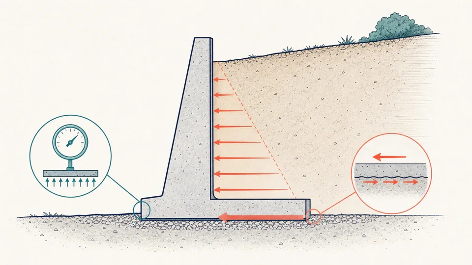
Editorial engineering scene with a retaining wall, a soil pressure gauge at the toe, and a separate sliding-resistance check on the base.
The illustration keeps foundation pressure and sliding reserve on different evidence tracks, matching the calculation instead of implying one combined safety score.
Retaining-wall operating-envelope reconciliationUnrounded calculation path
CheckCurrentMinimumMaximumBand position (%)Boundary result

LIVE CALCULATION PROCESS

Formula, substitution, and reconciliation

position = (current - lower bound) / (upper bound - lower bound) x 100%; inside only when both independent checks lie within their own bounds

The page normalizes pressure and sliding factor separately for display. A 65% pressure position is not combined with a 32% sliding position because kPa demand and a dimensionless stability ratio are not interchangeable. Negative clearance identifies how far an out-of-band value has crossed its nearest boundary.

    HOW TO USE

    Compare a current wall condition with documented service limits

    1. Copy the toe-pressure bounds from the same serviceability, monitoring, or design record; do not enter soil bearing capacity as a convenient upper band unless that is truly the defined limit.
    2. Enter the current toe pressure from the matching load combination and geometry revision.
    3. Enter the sliding-factor band and the current resistance-to-drive ratio using consistent factored or unfactored actions.
    4. Read the two positions and clearances separately, then investigate the mechanism that is nearest to or beyond its boundary.
    5. Archive the threshold source, wall revision, groundwater condition, and unrounded clearances with the inspection or design decision.

    SUBJECT FUNDAMENTALS

    Why an operating envelope is not a retaining-wall design

    Toe pressure
    The compressive contact demand near the wall toe. It can be sensitive to eccentricity and does not describe settlement by itself.
    Sliding factor
    Available sliding resistance divided by the corresponding horizontal driving action.
    Declared band
    A project-specific lower and upper boundary taken from a design, monitoring, or operating document.
    Boundary clearance
    The smaller signed distance from the current value to either bound; a negative value indicates an excursion.
    Load combination
    The specific collection and factoring of soil, surcharge, water, seismic, and other actions used to obtain the current result.
    Independent mechanism
    A check that retains its own units, assumptions, and acceptance rule rather than being averaged with unrelated checks.

    CALCULATION METHOD

    Normalize positions for communication, not for design substitution

    position = (current - lower bound) / (upper bound - lower bound) x 100%; inside only when both independent checks lie within their own bounds

    The page normalizes pressure and sliding factor separately for display. A 65% pressure position is not combined with a 32% sliding position because kPa demand and a dimensionless stability ratio are not interchangeable. Negative clearance identifies how far an out-of-band value has crossed its nearest boundary.

    DEFAULT CASE AUDIT TRAIL

    Symbols, units, substitution, and independent check

    SymbolMeaningUnit
    PminLower toe-pressure boundarykPa
    PmaxUpper toe-pressure boundarykPa
    PCurrent toe pressurekPa
    SminLower sliding-factor boundarydimensionless
    SmaxUpper sliding-factor referencedimensionless
    SCurrent sliding factordimensionless

    Default values

    • Pmin = 45 kPa, Pmax = 180 kPa, and P = 132 kPa.
    • Smin = 1.50, Smax = 2.50, and S = 1.82.

    Unit conversion

    • Pressure values already share kPa, while sliding factors are dimensionless; the two tracks are normalized separately and never averaged.

    Numerical substitution

    1. Pressure position = (132 - 45) / (180 - 45) x 100 = 64.444%.
    2. Sliding position = (1.82 - 1.50) / (2.50 - 1.50) x 100 = 32.000%.
    3. Pressure clearance = min(132 - 45, 180 - 132) = 48 kPa.
    4. Sliding clearance = min(1.82 - 1.50, 2.50 - 1.82) = 0.32.

    Named intermediate results

    • Pressure span: 135 kPa.
    • Sliding-factor span: 1.00.
    • Both signed clearances are positive, so neither default point crosses a boundary.

    Independent check:Reconstructing each current value from lower bound + position x span returns 132 kPa and 1.82 respectively; the combined status is inside only because both independent checks pass.

    DEEPER ANALYSIS

    Conditions that can move the point without changing the wall geometry

    Groundwater and drainage

    A blocked drain or higher water table can add hydrostatic drive and alter base contact. The current point is only meaningful with a dated water assumption.

    Eccentric contact

    Average base pressure can hide a toe peak or loss of heel contact. Use the actual pressure model that produced the entered value.

    Threshold provenance

    A monitoring alert, service limit, ultimate limit, and manufacturer recommendation are not the same boundary. Preserve the source and decision rule.

    WORKED DECISION CASES

    Two decisions this range check can support

    Post-storm inspection

    An engineer enters the recalculated toe pressure and sliding factor after a recorded water-level rise. Sliding remains inside its band, but toe pressure crosses the monitoring limit, so the foundation review is prioritized.

    Instrumentation trend review

    Monthly results remain inside both bands, yet sliding clearance narrows steadily. The trend triggers drainage inspection before an actual excursion occurs.

    Retaining-wall range terminology

    Contact pressure
    Normal stress transferred from the base to supporting soil.
    Eccentricity
    Offset between the resultant base force and the base centerline.
    Hydrostatic pressure
    Water pressure that increases with depth when drainage is ineffective.
    Sliding resistance
    Declared resistance from base friction, adhesion, passive resistance, keys, or other approved mechanisms.
    Excursion
    A result below the lower bound or above the upper bound.
    Global stability
    Potential movement of a larger soil-wall mass beyond the local base checks.

    EVIDENCE AND DATA LINEAGE

    Retain the envelope source and the condition that produced the point

    Keep the wall section and revision, soil parameters, groundwater level, drainage condition, surcharge and seismic assumptions, load-combination identifier, base-contact calculation, sliding-resistance components, units, timestamps, instrumentation calibration where applicable, entered boundaries, unrounded results, and the action taken after review.

    LIMITS AND EXCLUSIONS

    What this range page deliberately does not calculate

    • No active/passive pressure distribution, bearing capacity, settlement, overturning, structural reinforcement, seismic, liquefaction, or global-stability analysis is performed.
    • The page does not validate the entered bounds, pressure model, sliding resistance, instrumentation, or load combination.
    • An inside-envelope status is not an approval to construct, occupy, or defer a required inspection.

    RELIABLE SOURCES

    References for the method and its boundaries

    FREQUENTLY ASKED QUESTIONS

    Questions about the wall envelope result

    Why is there a minimum toe-pressure bound?

    Some monitoring plans use a lower band to identify loss of contact or a load-path change. If your project has no meaningful lower pressure bound, use the documented minimum rather than inventing one.

    Can I average the two positions?

    No. Pressure and sliding factor represent different mechanisms and units; averaging would hide the governing issue.

    Does 100% pressure position mean failure?

    It means the current value equals the entered upper boundary. What that boundary means depends on its source and decision rule.

    Can the sliding upper reference be arbitrary?

    It should come from the range you want to communicate. It does not create extra resistance or replace the required minimum.

    Does the page calculate lateral earth pressure?

    No. Enter a current pressure and sliding factor produced by the appropriate wall model.

    What should be done after an excursion?

    Follow the project response plan, verify measurements and assumptions, then have the responsible engineer evaluate the relevant mechanism.

    RELATED CALCULATORS

    Continue the engineering review

    IMPORTANT NOTE

    Use the output as a monitoring or review record, not a sealed design

    Retaining walls can fail through interacting geotechnical, hydraulic, structural, and construction mechanisms. A qualified professional must establish the governing model, limits, and response plan for the actual site.