EN

Engineering

Shaft Operating Range Calculator

Check a shaft operating point against continuous speed and torque limits, a separate peak-torque reference, and a critical-speed exclusion band.

SHAFT OPERATING RANGE

Keep continuous duty, peak torque, and resonance separation distinct

Speed can be in range while torque exceeds continuous duty, or both can look acceptable while operation sits too close to a critical speed. The page checks each condition separately.

Speed-range position-
Continuous torque utilization-
Peak torque reference-
Critical-speed separation-
Operating-envelope status-

ENGINEERING DECISION VIEW

Locate one operating point against four boundaries

Use the first failed row to direct review. Being below peak torque does not make a continuous overload acceptable.
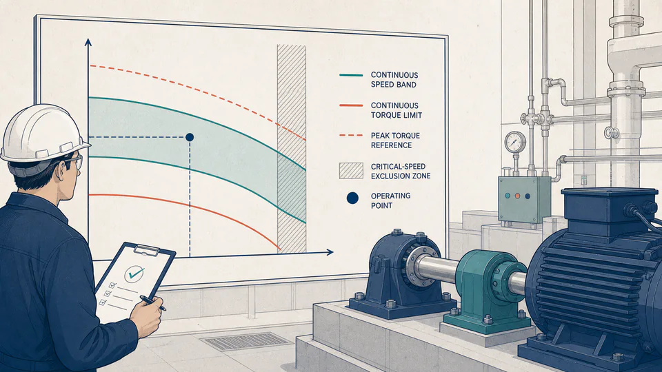
Editorial machine-room scene with one shaft point checked against speed, torque, peak, and resonance boundaries.
Four separate boundaries prevent a permissive peak value from hiding continuous overload or resonance proximity.
Shaft operating-envelope checksUnrounded calculation path
CheckCurrentLower / referenceUpper / limitPosition / utilizationDecision

LIVE CALCULATION PROCESS

Formula, substitution, and reconciliation

speed position = (N-Nmin)/(Nmax-Nmin); torque utilization = T/Tcontinuous; separation = |N-Ncritical|/Ncritical

Speed, continuous torque, peak reference, and critical-speed separation are separate ledger rows. Combined status requires speed in range, torque below continuous rating, and operation outside the exclusion band.

    HOW TO USE

    Screen a proposed continuous point

    1. Enter approved continuous speed bounds.
    2. Enter continuous and peak torque with their exact duty definitions.
    3. Enter current speed and torque from the same condition.
    4. Enter the nearest critical speed and required separation; investigate every failed row.
    5. Record the continuous and peak rating sources, peak duration, critical-mode identity, and current operating timestamp with the envelope result.

    SUBJECT FUNDAMENTALS

    Operating-envelope distinctions

    Continuous duty
    Load and speed sustainable under stated thermal and mechanical conditions.
    Peak torque
    Higher short-duration reference tied to time and repetition.
    Speed position
    Normalized location within continuous speed limits.
    Torque utilization
    Current torque divided by a declared boundary.
    Critical-speed exclusion
    Region intentionally avoided around resonance.
    Combined status
    Logical AND of independent conditions, never an average.

    CALCULATION METHOD

    Require every continuous condition

    speed position = (N-Nmin)/(Nmax-Nmin); torque utilization = T/Tcontinuous; separation = |N-Ncritical|/Ncritical

    Speed, continuous torque, peak reference, and critical-speed separation are separate ledger rows. Combined status requires speed in range, torque below continuous rating, and operation outside the exclusion band.

    DEFAULT CASE AUDIT TRAIL

    Symbols, units, substitution, and independent check

    SymbolMeaningUnit
    NminMinimum continuous speedrpm
    NmaxMaximum continuous speedrpm
    NopCurrent operating speedrpm
    TcContinuous torque limitN*m
    TpPeak torque referenceN*m
    NcIdentified critical speedrpm

    Default values

    • Nmin = 900 rpm, Nmax = 3,600 rpm, and Nop = 2,950 rpm.
    • Tc = 1,250 N*m, Tp = 1,800 N*m, current torque = 980 N*m, Nc = 4,100 rpm, and exclusion = 15%.

    Unit conversion

    • Speed and torque values already share rpm and N*m. Positions and utilizations are dimensionless ratios reported as percentages.

    Numerical substitution

    1. Speed position = (2,950 - 900) / (3,600 - 900) x 100 = 75.926%.
    2. Continuous utilization = 980 / 1,250 x 100 = 78.400%.
    3. Peak-reference utilization = 980 / 1,800 x 100 = 54.444%.
    4. Critical separation = |2,950 - 4,100| / 4,100 x 100 = 28.049%.

    Named intermediate results

    • Continuous speed span: 2,700 rpm.
    • Continuous torque reserve: 270 N*m.
    • Critical-speed separation exceeds the entered 15% exclusion.

    Independent check:The default point is inside the speed range, below continuous torque, and outside the critical-speed exclusion band; all three independent gates must pass for the combined status.

    DEEPER ANALYSIS

    Why rpm and torque are not the whole envelope

    Thermal memory

    Repeated peak events may accumulate heat even when each event is short.

    Different resonances

    Torsional and lateral modes require correct identification and excitation review.

    Connected equipment

    Couplings, gears, bearings, and driven machines may have narrower limits.

    WORKED DECISION CASES

    Two operating decisions

    Variable-speed uprate

    Speed and torque pass, but the new point enters the critical-speed exclusion band, stopping the uprate for rotor review.

    Low-speed high torque

    Torque is below peak but above continuous, so the point is rejected as continuous duty.

    Shaft operating terminology

    Duty cycle
    Sequence and duration of loads and speeds.
    Continuous rating
    Boundary valid without a short-time exception.
    Peak rating
    Temporary boundary for a specified event.
    Overspeed
    Operation above approved maximum speed.
    Critical speed
    Speed where a rotating mode aligns with excitation.
    Separation margin
    Relative distance from the critical-speed reference.

    EVIDENCE AND DATA LINEAGE

    Retain ratings with their duration and condition

    Keep rating sources, peak duration, measurements, critical-mode report, separation criterion, temperature, lubrication, connected-equipment limits, controls, and unrounded results.

    LIMITS AND EXCLUSIONS

    What the envelope excludes

    • No fatigue, thermal transient, acceleration, overspeed burst, rotor response, or connected-equipment analysis is included.
    • The page does not validate ratings, the critical-speed identity, or sensor accuracy.
    • A passing point does not approve start-up, shutdown, or upset operation.

    RELIABLE SOURCES

    References for the method and its boundaries

    FREQUENTLY ASKED QUESTIONS

    Questions about the envelope

    Why show peak utilization?

    It distinguishes continuous overload from exceeding even the transient reference.

    Can minimum speed be zero?

    This page is for a positive continuous range, not start-up or standstill.

    Is 15% universal?

    No; use the applicable manufacturer or project criterion.

    What if torque lies between continuous and peak?

    It needs a documented transient duty and remains outside the continuous envelope.

    Does the page assess start-up passage?

    No; that needs transient vibration and acceleration criteria.

    Can a pass release equipment?

    No; it only reconciles the entered point and boundaries.

    RELATED CALCULATORS

    Continue the engineering review

    IMPORTANT NOTE

    Use the narrowest verified system limit

    Operation must satisfy every governing equipment, process, control, vibration, thermal, and safety limit.