EN

Engineering

Shaft Sensitivity Calculator

Estimate how declared stiffness and supported-mass changes shift a shaft critical speed and its separation from an operating speed.

SHAFT CRITICAL-SPEED SENSITIVITY

Test whether stiffness or supported mass moves a resonance toward the operating point

Critical speed scales approximately with the square root of stiffness divided by mass for a consistent mode shape. This calculator applies explicit percentage changes to a validated base critical speed, then compares the shifted estimate with the actual operating speed and an entered exclusion band.

Shifted critical speed (rpm)-
Critical-speed change (rpm)-
Base separation from operation-
Shifted separation from operation-
Exclusion-band status-

ENGINEERING DECISION VIEW

Trace how a hardware change moves the resonance marker

If the shifted estimate enters the exclusion band, return to the rotor model or test plan. Do not move the operating speed or declare the design acceptable from this sensitivity alone.
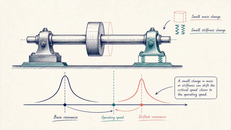
Editorial rotor-dynamics scene showing a shaft on bearings, a base resonance marker, and a shifted marker moving toward the operating-speed line after mass and stiffness changes.
The base model remains visible while the changed configuration moves one critical-speed estimate; the drawing does not imply a complete Campbell diagram.
Critical-speed sensitivity casesUnrounded calculation path
CaseCritical speed (rpm)Operating speed (rpm)Separation (%)Interpretation

LIVE CALCULATION PROCESS

Formula, substitution, and reconciliation

Ncrit,new = Ncrit,base x sqrt((1 + delta_k)/(1 + delta_m)); separation = |Ncrit - Noperating| / Noperating x 100%

The square-root scaling is a first-order sensitivity built on the entered base mode. Percentage changes are expressed as decimal multipliers, and stiffness or mass cannot fall to zero or below. It does not recompute bearing coefficients, mode shape, gyroscopic effects, or damping.

    HOW TO USE

    Use a known base mode to screen one configuration change

    1. Enter a base critical speed from an analysis or controlled test that represents the same shaft, supports, and mode of interest.
    2. Enter the operating speed that must remain separated from that mode.
    3. Estimate signed modal stiffness and supported-mass changes for the hardware modification; document how each percentage was obtained.
    4. Compare the shifted separation with the project or manufacturer band and escalate a near-band result to a full rotor-dynamic analysis.
    5. Tie each percentage change to a geometry, support, or attached-mass revision and retain the underlying rotor model before acting on the shifted critical speed.

    SUBJECT FUNDAMENTALS

    Rotor-dynamic ideas behind the square-root shift

    Critical speed
    Rotational speed at which an excitation order coincides with a system natural frequency.
    Modal stiffness
    Effective stiffness associated with one vibration mode, including shaft and support contributions.
    Modal mass
    Effective mass participating in the same mode, not necessarily total machine mass.
    Separation margin
    Relative distance between an operating speed and the critical-speed estimate.
    Damping
    Energy dissipation that limits resonance amplitude but does not eliminate the critical-speed location.
    Mode shape
    Spatial deformation pattern that defines which masses and supports participate in a natural mode.

    CALCULATION METHOD

    Treat square-root scaling as a local sensitivity, not a new rotor model

    Ncrit,new = Ncrit,base x sqrt((1 + delta_k)/(1 + delta_m)); separation = |Ncrit - Noperating| / Noperating x 100%

    The square-root scaling is a first-order sensitivity built on the entered base mode. Percentage changes are expressed as decimal multipliers, and stiffness or mass cannot fall to zero or below. It does not recompute bearing coefficients, mode shape, gyroscopic effects, or damping.

    DEFAULT CASE AUDIT TRAIL

    Symbols, units, substitution, and independent check

    SymbolMeaningUnit
    Nc,0Base modeled critical speedrpm
    NopOperating speedrpm
    Delta kEntered stiffness change%
    Delta mEntered modal-mass change%
    fkStiffness multiplierdimensionless
    fmMass multiplierdimensionless

    Default values

    • Nc,0 = 3,600 rpm and Nop = 2,950 rpm.
    • Delta k = -12%, Delta m = +8%, and exclusion band = 15%.

    Unit conversion

    • fk = 1 - 0.12 = 0.88 and fm = 1 + 0.08 = 1.08.
    • All speed comparisons remain in rpm; percentage changes become dimensionless multipliers before the square root.

    Numerical substitution

    1. Frequency multiplier = sqrt(0.88 / 1.08) = about 0.9027.
    2. Shifted critical speed = 3,600 x 0.9027 = about 3,249.6 rpm.
    3. Base separation = |3,600 - 2,950| / 2,950 x 100 = 22.034%.
    4. Shifted separation = |3,249.6 - 2,950| / 2,950 x 100 = about 10.16%.

    Named intermediate results

    • Stiffness multiplier: 0.88.
    • Modal-mass multiplier: 1.08.
    • Critical-speed shift: about -350.4 rpm.

    Independent check:The shifted separation is below the entered 15% exclusion requirement, so the default revision moves the critical speed into the exclusion band even though the base model was outside it.

    DEEPER ANALYSIS

    Changes the simple scaling cannot capture

    Bearing coefficients vary with speed and load

    Fluid-film and rolling-element supports can change stiffness and damping with temperature, clearance, preload, speed, and load.

    Gyroscopic effects split modes

    Disc inertia can move forward and backward whirl branches differently, so one scalar estimate may miss the relevant crossing.

    Excitation orders matter

    A critical speed is consequential only when imbalance, gear mesh, blade pass, electrical, or another excitation couples to the mode.

    WORKED DECISION CASES

    Two modification screens

    Heavier replacement impeller

    An 8% supported-mass increase and softer support estimate move the critical speed toward operating rpm. The result enters the declared band, so the change is held for rotor-model revision.

    Bearing-support stiffening

    A pedestal modification raises modal stiffness. The estimate moves the critical speed away from the operating point, but commissioning still includes a controlled run-up and vibration survey.

    Critical-speed sensitivity terminology

    Resonance
    Large response that may occur when excitation aligns with a natural mode.
    Whirl
    Lateral orbital motion of the rotating shaft centerline.
    Campbell diagram
    Plot of natural-frequency branches and excitation orders against rotational speed.
    Unbalance response
    Predicted or measured vibration caused by rotor mass eccentricity.
    Support stiffness
    Dynamic force-displacement relation of bearings, housings, pedestals, and foundations.
    Run-up
    Controlled speed increase used to observe vibration behavior through operating range.

    EVIDENCE AND DATA LINEAGE

    Retain the base mode and every assumption behind the percentages

    Keep the rotor model or test report, mode identification, shaft and disc geometry, support and bearing coefficients, operating-speed range, mass change and location, stiffness-change basis, damping assumptions, exclusion criterion source, units, calculation version, and unrounded base and shifted separations.

    LIMITS AND EXCLUSIONS

    What this first-order sensitivity does not predict

    • No Campbell diagram, mode-shape recomputation, damping, unbalance response, gyroscopic splitting, stability, torsional mode, bearing-coefficient, thermal, or transient analysis is performed.
    • The equation assumes the base and changed configurations represent the same mode and that percentage changes can be applied to its effective stiffness and mass.
    • A shifted critical speed does not establish acceptable vibration, stress, clearance, rub risk, or safe passage through resonance.

    RELIABLE SOURCES

    References for the method and its boundaries

    FREQUENTLY ASKED QUESTIONS

    Questions about the critical-speed estimate

    Why use the square root of stiffness over mass?

    A simple single-mode natural frequency follows that relationship. It is useful for local sensitivity when the base mode remains comparable.

    Can I enter negative changes?

    Yes, but neither stiffness nor mass may be reduced by 100% or more.

    Is the exclusion percentage universal?

    No. Use the applicable project, manufacturer, or analysis criterion.

    Does being outside the band prove vibration is acceptable?

    No. Response amplitude, damping, balance, alignment, excitation, and other modes still matter.

    Should separation use operating speed or critical speed as denominator?

    This page uses operating speed and states that convention explicitly; keep the same convention when comparing criteria.

    Can I use total machine mass?

    Only if it represents the modal mass change for the same mode. A component far from the mode antinode may contribute little.

    RELATED CALCULATORS

    Continue the engineering review

    IMPORTANT NOTE

    Rotor changes require model or test confirmation

    Use this page to decide whether a configuration change deserves deeper rotor-dynamic work. High-speed machinery changes should be reviewed under the manufacturer and project procedures by qualified rotating-equipment personnel.