EN

Engineering

Shaft Safety Factor Calculator

Calculate solid-shaft bending stress, torsional shear, von Mises equivalent stress, and a yield-based safety factor against an entered requirement.

SHAFT SAFETY FACTOR

Combine bending and torsion before comparing a solid shaft with yield

A shaft that carries torque often carries bending at the same section. This calculator keeps the two stress components visible, combines them with the von Mises criterion, and reports both the raw yield ratio and utilization against the entered design-factor requirement.

Bending stress (MPa)-
Torsional shear (MPa)-
von Mises stress (MPa)-
Yield safety factor-
Required-factor utilization-
Screen status-

ENGINEERING DECISION VIEW

See how two nominal stresses meet at the checked shaft section

Use a low factor or high utilization to revisit section geometry, loading, material basis, and stress raisers. Even a passing nominal-yield screen still needs fatigue, keyway, shoulder, surface, reliability, and deflection evaluation.
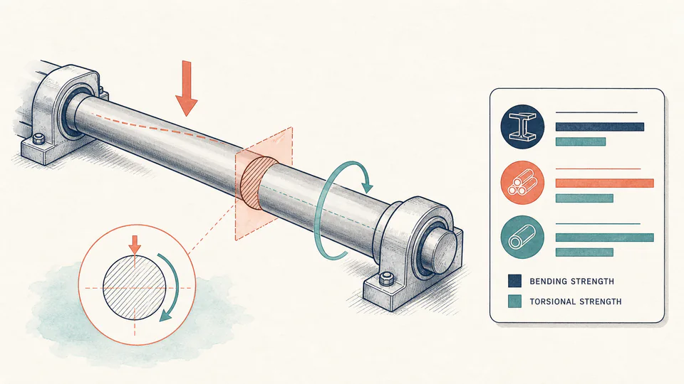
Editorial engineering cutaway of a solid rotating shaft under a bending arrow and a torsion arrow, with the critical cross-section highlighted.
The highlighted section is where bending and torque must refer to the same geometry before the equivalent-stress comparison has meaning.
Solid-shaft combined-stress ledgerUnrounded calculation path
CheckAction / stress 1Diameter / stress 2Result (MPa or factor)Equation / decision

LIVE CALCULATION PROCESS

Formula, substitution, and reconciliation

sigma_b = 32M/(pi*d^3); tau = 16T/(pi*d^3); sigma_vm = sqrt(sigma_b^2 + 3*tau^2); n = Sy/sigma_vm

The equations use nominal stresses for a solid circular shaft. Bending moment and torque are converted from N*m to N*mm so stress resolves to N/mm2, numerically equal to MPa. The required-factor utilization equals sigma_vm times the entered factor divided by yield strength.

    HOW TO USE

    Check one shaft section with consistent actions and geometry

    1. Select the physical shaft section and enter its net solid diameter; do not use a remote nominal diameter if a shoulder, groove, or keyway controls.
    2. Enter bending moment and torque from the same load case at that section.
    3. Enter the approved material yield value and the project-required comparison factor.
    4. Review the separate nominal stresses, then the von Mises result; follow with fatigue and stress-concentration checks before design acceptance.
    5. Record the checked section, load case, material certificate basis, and omitted stress raisers before treating the nominal screen as engineering evidence.

    SUBJECT FUNDAMENTALS

    Stress concepts behind the combined-yield screen

    Nominal bending stress
    Elastic outer-fibre stress for a smooth solid circular section under bending.
    Nominal torsional shear
    Elastic surface shear stress for a smooth solid circular section under torque.
    von Mises stress
    Distortion-energy equivalent stress used to compare a multi-axial ductile-metal state with uniaxial yield.
    Yield safety factor
    Entered yield strength divided by the calculated equivalent stress.
    Stress concentration
    Local amplification caused by shoulders, fillets, keyways, grooves, holes, or splines.
    Load case
    A defined simultaneous combination of radial forces, axial forces, torque, transients, and support reactions.

    CALCULATION METHOD

    Preserve the stress components before applying the ductile-yield criterion

    sigma_b = 32M/(pi*d^3); tau = 16T/(pi*d^3); sigma_vm = sqrt(sigma_b^2 + 3*tau^2); n = Sy/sigma_vm

    The equations use nominal stresses for a solid circular shaft. Bending moment and torque are converted from N*m to N*mm so stress resolves to N/mm2, numerically equal to MPa. The required-factor utilization equals sigma_vm times the entered factor divided by yield strength.

    DEFAULT CASE AUDIT TRAIL

    Symbols, units, substitution, and independent check

    SymbolMeaningUnit
    dNet solid-shaft diametermm
    MBending moment at the checked sectionN*m
    TTorque at the same sectionN*m
    sigma_bNominal bending stressMPa
    tauNominal torsional shearMPa
    SyEntered yield strengthMPa

    Default values

    • d = 50 mm, M = 850 N*m, and T = 1,200 N*m.
    • Sy = 355 MPa and required yield factor = 1.50.

    Unit conversion

    • M = 850,000 N*mm and T = 1,200,000 N*mm.
    • Because 1 MPa equals 1 N/mm2, the solid-section equations return MPa directly.

    Numerical substitution

    1. sigma_b = 32 x 850,000 / (pi x 50^3) = 69.265 MPa.
    2. tau = 16 x 1,200,000 / (pi x 50^3) = 48.892 MPa.
    3. sigma_vm = sqrt(69.265^2 + 3 x 48.892^2) = about 109.40 MPa.
    4. n = 355 / 109.40 = about 3.25.

    Named intermediate results

    • Nominal bending stress: about 69.27 MPa.
    • Nominal torsional shear: about 48.89 MPa.
    • von Mises equivalent stress: about 109.40 MPa.

    Independent check:The allowable equivalent stress at n = 1.50 is 355 / 1.50 = 236.67 MPa; the default equivalent stress is lower, and multiplying utilization by the raw factor recovers the required-factor comparison.

    DEEPER ANALYSIS

    Why nominal yield is only one shaft-design gate

    Fatigue usually governs rotating bending

    A surface point on a rotating shaft cycles between tension and compression. Endurance, mean stress, reliability, size, surface finish, and notch sensitivity may control well below yield.

    Geometry changes the local problem

    A keyway or shoulder needs the correct local diameter and stress-concentration treatment. Reducing yield strength by an arbitrary percentage is not a substitute.

    Deflection changes bearing and gear behavior

    A shaft may remain below yield yet misalign bearings, change gear contact, or exceed runout and vibration limits.

    WORKED DECISION CASES

    Two uses of the nominal combined-stress result

    Gearbox intermediate shaft screen

    Reaction analysis gives bending and torque at a shoulder. The nominal factor is acceptable, but the fillet and rotating-bending fatigue check is then identified as governing work.

    Overload investigation

    A recorded torque event raises von Mises stress close to yield. The exported calculation preserves the event load and section so inspection and residual-life decisions use the same evidence.

    Shaft strength terminology

    Section modulus
    Geometric property relating bending moment to nominal bending stress.
    Polar moment
    Geometric property relating torque to torsional shear.
    Equivalent stress
    Scalar representation of a combined stress state for a selected failure criterion.
    Ductile material
    Material capable of appreciable plastic deformation before fracture under relevant conditions.
    Endurance limit
    Stress-amplitude concept used in fatigue design for applicable materials and conditions.
    Critical section
    Location where geometry, stress, material, and load combination make failure most likely.

    EVIDENCE AND DATA LINEAGE

    Retain the checked section and the source of simultaneous loads

    Keep the shaft drawing and revision, local diameter, shoulders and keyways, material specification and heat treatment, yield basis, bearing and gear reactions, bending-moment and torque diagrams, load-case identifier, units, required-factor source, unrounded stresses, and the separate fatigue and deflection review.

    LIMITS AND EXCLUSIONS

    What the nominal von Mises screen excludes

    • No fatigue, stress concentration, notch sensitivity, surface finish, size, reliability, corrosion, temperature, residual stress, fracture, buckling, or creep calculation is included.
    • The equations apply to a solid circular elastic section and do not cover hollow, tapered, splined, cracked, plastically deformed, or composite shafts.
    • The page does not determine loads, material allowables, a required safety factor, or compliance with a governing design standard.

    RELIABLE SOURCES

    References for the method and its boundaries

    FREQUENTLY ASKED QUESTIONS

    Questions about the shaft safety factor

    Does the factor include a keyway?

    No. Use the net section and the appropriate fatigue and stress-concentration treatment for the actual keyway geometry.

    Why combine stresses with von Mises?

    It is a common ductile-yield criterion for combined normal and shear stress; another criterion may govern specific materials or standards.

    Can bending or torque be zero?

    Yes. The formula then reduces to the remaining stress component, but both cannot be zero if a finite safety factor is to be interpreted.

    Does a factor of 1.5 mean the shaft is safe?

    It only clears the entered nominal-yield comparison. Fatigue, dynamics, deflection, connections, material condition, and code requirements remain.

    Should peak or average torque be entered?

    Use the load case required by the decision: peak for overload/yield, and a full load spectrum for fatigue.

    Can this be used for a hollow shaft?

    No. Hollow shafts need the correct outer and inner diameter section properties.

    RELATED CALCULATORS

    Continue the engineering review

    IMPORTANT NOTE

    A passing nominal factor is not a release-to-service decision

    Shaft failure can cause high-energy equipment hazards. Final design and continued-service decisions require verified loads, geometry, material, manufacturing details, fatigue and dynamic analysis, guarding, inspection, and review by the responsible engineer.