Keyway fatigue behavior
Key depth, end shape, fit, fillet, surface, and notch sensitivity affect local fatigue. A single reduction cannot represent all geometries.
Engineering
Solve the remaining torque capacity of a solid shaft after bending stress, design factor, and a declared keyway reduction are applied to a von Mises allowable.
SHAFT COMBINED CAPACITY
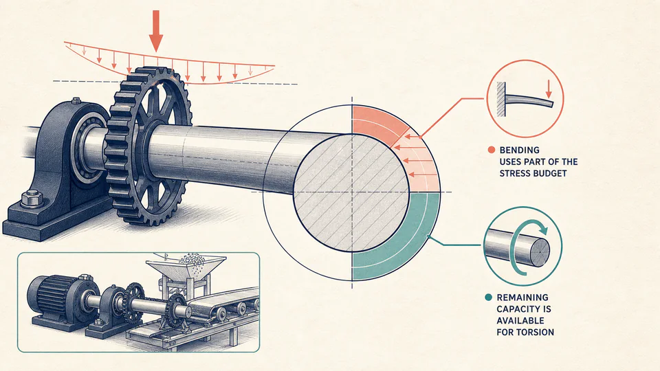
Torque capacity cannot be assessed independently when the checked section also carries bending. This calculator derives an entered-model allowable stress, calculates nominal bending stress, and solves the von Mises relationship for the torsional capacity that remains.
ENGINEERING DECISION VIEW
If bending alone consumes the allowable, the page stops instead of reporting imaginary torsional capacity. A positive margin supports only this nominal-yield screen and must be followed by local fatigue, geometry, and deflection checks.
| Capacity step | Input / stress | Geometry / comparison | Result | Interpretation |
|---|
LIVE CALCULATION PROCESS
sigma_allow = Sy/n x (1 - keyway reduction); tau_allow = sqrt((sigma_allow^2 - sigma_b^2)/3); Tcap = tau_allow*pi*d^3/16
The method first applies the entered design factor and declared keyway reduction to yield strength. Nominal bending stress is subtracted through the von Mises interaction, not by linearly subtracting percentages. The remaining allowable shear is converted to torque for a solid circular section.
HOW TO USE
SUBJECT FUNDAMENTALS
CALCULATION METHOD
The method first applies the entered design factor and declared keyway reduction to yield strength. Nominal bending stress is subtracted through the von Mises interaction, not by linearly subtracting percentages. The remaining allowable shear is converted to torque for a solid circular section.
DEFAULT CASE AUDIT TRAIL
| Symbol | Meaning | Unit |
|---|---|---|
| d | Net solid-shaft diameter | mm |
| M | Applied bending moment | N*m |
| Ta | Applied torque | N*m |
| Sy | Entered yield strength | MPa |
| nd | Entered design factor | dimensionless |
| r | Remaining strength factor after reduction | dimensionless |
Independent check:Substituting the calculated capacity torque back into sqrt(sigma_b^2 + 3 tau^2) returns the reduced allowable stress; the 1,100 N*m default demand remains below capacity.
DEEPER ANALYSIS
Key depth, end shape, fit, fillet, surface, and notch sensitivity affect local fatigue. A single reduction cannot represent all geometries.
Repeated torque, rotating bending, starts, stops, and shock loads require alternating and mean-stress treatment.
Heat treatment, decarburization, residual stress, corrosion, wear, repairs, and dimensional tolerances can invalidate the nominal input.
WORKED DECISION CASES
A higher-torque coupling is proposed on an existing shaft. The calculation shows bending already consumes much of the entered allowance, so a detailed shoulder and keyway fatigue review is commissioned.
Two concept diameters are checked with the same load case. Because capacity scales strongly with diameter cubed, the ledger shows why a small diameter change materially affects torque margin.
EVIDENCE AND DATA LINEAGE
Retain the drawing revision, local diameter, keyway and shoulder details, applied moment and torque diagrams, load-case timing, yield specification, heat treatment, design-factor source, reduction-factor rationale, unit conversions, unrounded stresses and capacity, and the subsequent fatigue and deflection checks.
LIMITS AND EXCLUSIONS
RELIABLE SOURCES
FREQUENTLY ASKED QUESTIONS
The von Mises equation has no real remaining shear solution once nominal bending reaches the entered allowable.
No. It is an explicit user-entered screening assumption and must not replace geometry-specific analysis.
Yes, for a pure-torsion screen, provided the real section truly has negligible bending.
Nominal bending and torsional stresses vary inversely with diameter cubed for a solid circular section.
No. It is a nominal static-yield interaction only.
Not with this stated ductile-yield model unless the governing design method explicitly establishes a different basis.
RELATED CALCULATORS
Calculate the factor at one entered combination rather than solving capacity.
Evaluate heat and delivered power without confusing energy loss with strength reserve.
IMPORTANT NOTE
Final shaft capacity requires the governing standard, verified load spectrum, full geometry, material and manufacturing condition, fatigue and dynamics, inspection, and responsible engineering approval.