EN

Engineering

Shaft Loss Calculator

Convert bearing and seal friction torque into power loss at operating speed, add windage or churning loss, and reconcile shaft input power to delivered output and heat load.

SHAFT POWER LOSS

Translate friction torque into the heat and output power it creates at speed

A torque loss that seems small at low speed can become a material heat load at high rpm. The calculator converts bearing and seal friction separately, adds windage or churning, and checks the energy balance.

Bearing + seal loss (kW)-
Total shaft loss (kW)-
Delivered output power (kW)-
Shaft-stage efficiency-
Heat rejection rate (kW)-

ENGINEERING DECISION VIEW

Separate drag paths before they become one heat load

Investigate the largest evidenced loss path. Do not assign a temperature rise to bearing friction without checking lubrication, seals, windage, alignment, cooling, and the selected boundary.
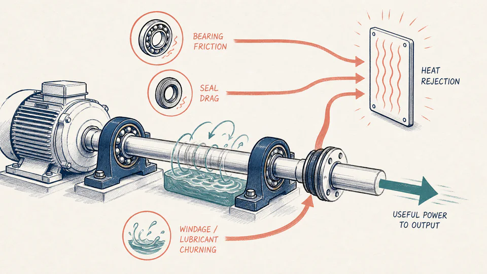
Editorial cutaway of a rotating shaft with bearing friction, seal drag, and windage leading to a heat-rejection panel.
Each loss remains attached to its physical source before speed converts it to thermal duty.
Shaft loss and thermal balanceUnrounded calculation path
Loss pathTorque (N*m)Speed (rpm)Power (kW)Balance meaning

LIVE CALCULATION PROCESS

Formula, substitution, and reconciliation

Pfriction = (Tbearing + Tseal) x 2*pi*N/60,000; Ploss = Pfriction + Pwindage; Pout = Pin - Ploss

Each running torque is converted to kilowatts at the same operating speed. Windage is entered directly as power because it normally comes from a separate test or model. At steady state the total lost mechanical power is also the first-order heat-rejection duty.

    HOW TO USE

    Reconcile input power, losses, heat, and output

    1. Define the rotating assembly boundary and enter input power at the same steady operating point as the loss data.
    2. Enter bearing and seal running torque only for components inside that boundary.
    3. Enter windage or lubricant-churning loss as a separate documented kW term.
    4. Review output and heat rate together; at steady state the cooling path must reject the lost power.
    5. Archive the torque-loss evidence, lubricant state, temperature, and boundary definition with the unrounded power balance for later thermal reconciliation.

    SUBJECT FUNDAMENTALS

    Loss mechanisms behind the balance

    Bearing friction
    Rolling, sliding, and lubricant resistance inside the bearing arrangement.
    Seal drag
    Torque required to shear or deform sealing elements.
    Windage
    Aerodynamic loss from rotating surfaces moving gas.
    Churning
    Power used to move lubricant around rotating components.
    Heat rejection
    Thermal power that must leave the assembly at steady temperature.
    Boundary balance
    Input equals useful output plus loss for a steady defined system.

    CALCULATION METHOD

    Convert torque at the real speed, then close the balance

    Pfriction = (Tbearing + Tseal) x 2*pi*N/60,000; Ploss = Pfriction + Pwindage; Pout = Pin - Ploss

    Each running torque is converted to kilowatts at the same operating speed. Windage is entered directly as power because it normally comes from a separate test or model. At steady state the total lost mechanical power is also the first-order heat-rejection duty.

    DEFAULT CASE AUDIT TRAIL

    Symbols, units, substitution, and independent check

    SymbolMeaningUnit
    PinPower entering the shaft boundarykW
    NRotational speedrpm
    TbBearing friction torqueN*m
    TsSeal friction torqueN*m
    PwEntered windage or churning losskW
    omegaAngular speedrad/s

    Default values

    • Pin = 95 kW and N = 3,600 rpm.
    • Tb = 8.5 N*m, Ts = 4.2 N*m, and Pw = 1.4 kW.

    Unit conversion

    • omega = 2 x pi x 3,600 / 60 = 376.991 rad/s.
    • Torque x angular speed is watts; divide by 1,000 for kW.

    Numerical substitution

    1. Bearing loss = 8.5 x 376.991 / 1,000 = 3.204 kW.
    2. Seal loss = 4.2 x 376.991 / 1,000 = 1.583 kW.
    3. Total loss = 3.204 + 1.583 + 1.400 = 6.188 kW.
    4. Output power = 95 - 6.188 = 88.812 kW.

    Named intermediate results

    • Angular speed: 376.991 rad/s.
    • Torque-dependent friction loss: 4.788 kW.
    • Total rejected heat rate: 6.188 kW.

    Independent check:88.812 kW delivered output + 6.188 kW total loss equals 95.000 kW input within display rounding; each loss term remains separately identifiable.

    DEEPER ANALYSIS

    Why losses move with operating condition

    Lubricant viscosity and fill

    Temperature, grade, level, and grease quantity can materially shift friction and churning.

    Breakaway versus running torque

    Starting torque is not stabilized running drag; use the quantity matching the decision.

    Nonlinear speed behavior

    Power is linear in speed for fixed torque, but the loss torque itself often changes with speed and temperature.

    WORKED DECISION CASES

    Two loss investigations

    Bearing temperature review

    A lubrication change raises running torque; the page converts it into heat load for comparison with cooler capacity.

    Seal retrofit

    A lower-drag seal saves 2 N*m; operating rpm turns that change into a traceable continuous power saving.

    Shaft loss terminology

    Running torque
    Resistance torque after start-up settles.
    Breakaway torque
    Torque required to initiate motion.
    Thermal steady state
    Condition in which stored heat no longer changes materially.
    Windage coefficient
    Parameter relating geometry and gas conditions to aerodynamic loss.
    Churning regime
    Lubrication condition governing fluid drag.
    Power balance
    Equality between input, output, stored-energy change, and loss.

    EVIDENCE AND DATA LINEAGE

    Retain the operating condition behind every loss

    Keep speed and load, input-power method, bearing and seal details, lubrication grade and temperature, windage method, alignment, sampling interval, cooling condition, and the unrounded balance.

    LIMITS AND EXCLUSIONS

    What this loss model excludes

    • No detailed bearing, lubricant, seal, windage, transient thermal, or cooling-system model is included.
    • Friction torque and windage are user-supplied rather than inferred.
    • The output does not establish bearing life, seal life, vibration, shaft strength, or acceptable temperature.

    RELIABLE SOURCES

    References for the method and its boundaries

    FREQUENTLY ASKED QUESTIONS

    Questions about shaft loss

    Why does heat rate equal lost kW?

    At steady state, mechanical loss becomes heat that must leave the boundary.

    Can bearing torque include seals?

    Yes only when separately entered seal torque is zero and the combined source is documented.

    Is windage constant with rpm?

    Usually not; enter the value for this speed.

    Why reject losses above input?

    A steady passive assembly cannot dissipate more power than enters it.

    Can motor electrical input be used?

    Only after motor losses are included or the boundary is redefined.

    Does lower loss prove acceptable temperature?

    No; heat transfer, ambient condition, oil flow, and geometry still govern temperature.

    RELATED CALCULATORS

    Continue the engineering review

    IMPORTANT NOTE

    Confirm losses at the real operating condition

    Use manufacturer data, calibrated tests, or validated models. Thermal and mechanical acceptance requires the full duty cycle, cooling system, lubrication state, and responsible engineering review.