EN

Engineering

Shaft Efficiency Calculator

Convert measured shaft torque and speed into output power, compare it with upstream input power, and separate declared auxiliary loss from the unexplained balance.

SHAFT EFFICIENCY

Reconcile torque-speed output with the power that entered the shaft train

Efficiency is only credible when input and output measurements refer to the same operating point. The calculator derives mechanical output from torque and rpm, removes separately measured auxiliary loss, and exposes any remaining energy imbalance instead of hiding it inside a single percentage.

Torque-speed output (kW)-
Measured efficiency-
Total input-output loss (kW)-
Unexplained balance (kW)-
Input less auxiliary loss (kW)-

ENGINEERING DECISION VIEW

Follow power across the measurement planes

A material unexplained balance is a measurement and boundary problem before it is an efficiency conclusion. Check timestamp alignment, sensor location, torque sign, speed basis, and whether auxiliaries sit inside or outside the stated boundary.
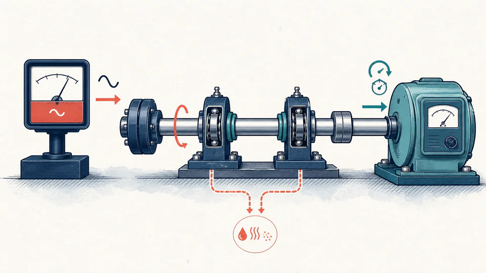
Editorial cutaway of a rotating shaft between an input power meter and a torque-speed dynamometer, with a small separate loss path for bearings and seals.
Input power, measured shaft output, and declared auxiliary losses stay visible as separate quantities so the residual cannot disappear into a generic efficiency badge.
Shaft power and loss balanceUnrounded calculation path
Balance itemTorque / inputSpeed / comparisonPower (kW)Evidence meaning

LIVE CALCULATION PROCESS

Formula, substitution, and reconciliation

Pout = 2*pi*N*T / 60,000; efficiency = Pout / Pin x 100%; unexplained loss = Pin - Pout - declared auxiliary loss

Torque in newton-metres multiplied by angular speed gives watts; division by 1,000 gives kilowatts. The input-output loss is then split between the separately entered auxiliary loss and the unexplained balance. No efficiency value is clipped to look plausible.

    HOW TO USE

    Build an efficiency result that can be reconciled later

    1. Define the system boundary first: identify exactly where input power is measured and where torque and speed are measured.
    2. Enter torque and rpm from the same steady operating interval; do not pair a peak torque with an average speed.
    3. Enter only auxiliary loss supported by a separate measurement or documented estimate, and keep its method with the record.
    4. Review output power and the unexplained balance before accepting the efficiency percentage.
    5. Save synchronized raw samples and the measurement-plane sketch so a later reviewer can reproduce the residual instead of seeing only the efficiency percentage.

    SUBJECT FUNDAMENTALS

    Power-measurement concepts behind shaft efficiency

    Angular speed
    Rotational speed expressed in radians per second; omega equals 2*pi*rpm/60.
    Torque-speed power
    Instantaneous mechanical power produced by torque acting at angular speed.
    Measurement plane
    Physical section of the drivetrain where a sensor or inferred quantity applies.
    System boundary
    Declared equipment included in the input-output balance, such as couplings, bearings, seals, or gearbox stages.
    Auxiliary loss
    A separately evidenced loss that sits inside the chosen boundary but is not part of useful output.
    Energy residual
    Input minus accounted output and known losses; a diagnostic for missing loss or inconsistent measurements.

    CALCULATION METHOD

    Use a power balance that preserves the unexplained residual

    Pout = 2*pi*N*T / 60,000; efficiency = Pout / Pin x 100%; unexplained loss = Pin - Pout - declared auxiliary loss

    Torque in newton-metres multiplied by angular speed gives watts; division by 1,000 gives kilowatts. The input-output loss is then split between the separately entered auxiliary loss and the unexplained balance. No efficiency value is clipped to look plausible.

    DEFAULT CASE AUDIT TRAIL

    Symbols, units, substitution, and independent check

    SymbolMeaningUnit
    PinMeasured power entering the chosen boundarykW
    TMeasured output torqueN*m
    NOutput rotational speedrpm
    omegaOutput angular speedrad/s
    PoutTorque-speed output powerkW
    PauxSeparately evidenced auxiliary losskW

    Default values

    • Pin = 75 kW, T = 225 N*m, and N = 2,950 rpm.
    • Paux = 2.2 kW inside the declared measurement boundary.

    Unit conversion

    • omega = 2 x pi x 2,950 / 60 = 308.923 rad/s.
    • Torque times rad/s gives watts; divide by 1,000 to report kilowatts.

    Numerical substitution

    1. Pout = 225 x 308.923 / 1,000 = 69.508 kW.
    2. Measured efficiency = 69.508 / 75 x 100 = 92.677%.
    3. Total input-output loss = 75 - 69.508 = 5.492 kW.
    4. Unexplained balance = 5.492 - 2.2 = 3.292 kW.

    Named intermediate results

    • Angular speed: 308.923 rad/s.
    • Declared auxiliary share: 2.200 kW.
    • Unexplained residual: 3.292 kW.

    Independent check:69.508 kW output + 2.200 kW declared auxiliary loss + 3.292 kW unexplained balance equals the 75.000 kW input within display rounding.

    DEEPER ANALYSIS

    Why plausible percentages can still be wrong

    Non-synchronous data

    Torque, speed, and input power sampled at different times can create a false loss or an apparent efficiency above 100%.

    Sensor and plane mismatch

    A motor electrical input, coupling torque, and downstream speed do not describe the same boundary unless intervening losses are explicitly included.

    Transient operation

    Acceleration stores kinetic energy in the rotating inertia. A steady-state input-output balance cannot be applied blindly during run-up or coast-down.

    WORKED DECISION CASES

    Two practical efficiency investigations

    Commissioning a driven pump

    A technician compares motor-side input power with downstream shaft torque and rpm. A 4 kW residual leads to a review of coupling alignment and the location of the auxiliary oil-pump load.

    Post-maintenance comparison

    The same operating point is recorded before and after a seal replacement. Output power is unchanged but declared seal loss falls, providing a traceable maintenance benefit.

    Shaft power-balance terminology

    Dynamometer
    Instrument that measures torque, often together with rotational speed.
    Mechanical power
    Rate of work transmitted through rotation.
    Parasitic loss
    Power consumed by friction, windage, seals, auxiliaries, or other non-useful paths.
    Steady state
    Interval in which stored rotational energy is not materially changing.
    Calibration
    Documented relationship between sensor indication and reference values.
    Residual
    Unexplained difference remaining after known balance terms are applied.

    EVIDENCE AND DATA LINEAGE

    Retain synchronized measurements and the physical boundary

    Keep instrument IDs, calibration status, sampling interval, averaging method, torque sign convention, rpm source, input-power method, measurement-plane diagram, included equipment, declared auxiliary-loss evidence, ambient and lubrication condition, raw data, and unrounded balance.

    LIMITS AND EXCLUSIONS

    What this steady-state balance does not establish

    • No transient inertia, torsional vibration, electrical harmonics, thermal soak, uncertainty propagation, or efficiency-map interpolation is included.
    • The calculator does not validate sensor calibration, torque sign, measurement synchrony, or the chosen system boundary.
    • Efficiency does not demonstrate shaft strength, coupling capacity, bearing life, alignment, or acceptable operating temperature.

    RELIABLE SOURCES

    References for the method and its boundaries

    FREQUENTLY ASKED QUESTIONS

    Questions about torque-speed efficiency

    Why can the calculator reject output above input?

    A small difference can come from uncertainty, but a material excess usually means mismatched units, signs, timestamps, or measurement planes.

    Should motor efficiency be entered?

    Only if you are converting electrical motor input to shaft input. This page expects the input power already defined at the selected shaft boundary.

    Can auxiliary loss be zero?

    Yes when no separate internal loss is being claimed, but the unexplained residual then carries all unaccounted loss.

    Does the result include gearbox efficiency?

    Only if the gearbox lies inside the boundary between the entered input and measured output.

    What rpm should I use for variable speed?

    Use the speed synchronized with the torque and input-power sample or integrate a time-resolved balance.

    Is the unexplained balance automatically friction?

    No. It may reflect heat, windage, measurement bias, timing mismatch, or a boundary definition error.

    RELATED CALCULATORS

    Continue the engineering review

    IMPORTANT NOTE

    Do not use a reconciled power balance as a mechanical integrity approval

    Use calibrated, synchronized measurements and a defined system boundary. Equipment selection and acceptance still require the governing manufacturer procedures, design standard, uncertainty analysis, and competent engineering review.