Phase imbalance is not visible in total kVA
One phase can approach conductor or winding limits while average three-phase kVA looks acceptable. Preserve per-phase currents, neutral current, and voltage unbalance.
Engineering
Convert measured single- or three-phase voltage and current to kVA, apply documented demand and growth assumptions, compare with transformer nameplate rating, and estimate real power and losses.
TRANSFORMER DEMAND SCREEN
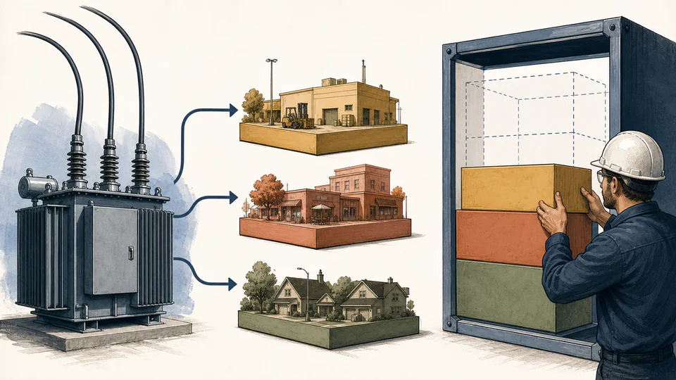
This calculator helps electrical engineers and facility planners translate measured line voltage and current into apparent load, then apply an entered demand factor and future-growth allowance before comparing with transformer nameplate kVA. Power factor converts planned apparent load to real output, while entered efficiency provides a screening loss estimate. The page does not determine permitted loading, protection, conductor ampacity, harmonics, temperature rise, or code compliance.
TRANSFORMER DEMAND SCREEN
Use planned kVA and loading percentage to identify whether detailed transformer and feeder studies are required. Do not infer allowable overload from a value below or above 100%; nameplate, loading guides, ambient, thermal history, insulation life, harmonics, and protection govern that decision.
| Load stage | Electrical value A | Factor / value B | Calculated value | Unit / basis |
|---|
CURRENT CALCULATION PROCESS
S_measured = k_phase V I /1000; S_plan = S_measured f_demand(1+g); loading = S_plan/S_rated; P_out = S_plan PF
The phase multiplier is one for single-phase and √3 for balanced three-phase using line-to-line voltage and line current. Demand factor reduces the measured reference apparent load to the diversified planning basis; growth is then added once. kVA loading is compared directly with nameplate kVA, while power factor and efficiency are used only for a separate real-power and loss estimate.
| Input / symbol | Engineering meaning and unit | Current value |
|---|---|---|
| phases | Phase count (1 or 3) — Three-phase uses √3 × line-to-line voltage × line current. | 3 |
| voltageV | Measured line voltage (V) — Use line-to-line voltage for three-phase and terminal voltage for single-phase. | 400 |
| measuredCurrentA | Measured line current (A) — Use the representative maximum or profile statistic for the planning case. | 520 |
| powerFactor | Power factor (%) — Total true kW divided by kVA at the assessed condition. | 88 |
| demandFactor | Demand factor (%) — Diversified peak divided by the connected or measured reference load. | 82 |
| futureGrowth | Future growth allowance (%) — Applied once to diversified kVA; do not duplicate loads already included. | 18 |
| transformerRatingKva | Transformer nameplate rating (kVA) — Base nameplate rating before any approved ambient or duty adjustment. | 630 |
| efficiency | Transformer efficiency (%) — Planning efficiency at a comparable load and power factor. | 98.4 |
Intermediate values remain unrounded until display formatting.
HOW TO USE THIS MODEL
TRANSFORMER DEMAND SCREEN FUNDAMENTALS
MODEL AND FORMULA
The phase multiplier is one for single-phase and √3 for balanced three-phase using line-to-line voltage and line current. Demand factor reduces the measured reference apparent load to the diversified planning basis; growth is then added once. kVA loading is compared directly with nameplate kVA, while power factor and efficiency are used only for a separate real-power and loss estimate.
DEEPER ENGINEERING ANALYSIS
One phase can approach conductor or winding limits while average three-phase kVA looks acceptable. Preserve per-phase currents, neutral current, and voltage unbalance.
Nonlinear loads increase RMS current, eddy losses, neutral current, and distortion. kVA alone does not determine K-factor suitability or harmonic derating.
Ambient, cooling mode, previous load, hot-spot temperature, insulation age, duration, and emergency criteria affect permissible loading. A static nameplate ratio is only a trigger for detailed study.
WORKED DECISION CASES
Interval data establishes the existing coincident peak, while charger schedules and managed charging define growth. A blanket percentage can double count chargers already operating during the baseline period.
Measured kVA is under nameplate, but waveform distortion and phase current demand a harmonic and thermal assessment before adding another drive bank.
TECHNICAL LANGUAGE
EVIDENCE AND DATA LINEAGE
Retain transformer nameplate and cooling class, vector group, tap position, ambient and enclosure conditions, interval voltage/current/kW/kVA/PF data, per-phase and neutral currents, harmonic spectrum, demand interval and factor derivation, existing and planned load list, coincidence assumptions, growth project register, efficiency source, protection settings, feeder one-line, prior thermal or dissolved-gas evidence as applicable, and the unrounded load ledger. Timestamp every dataset so later projects are not counted twice.
LIMITS AND EXCLUSIONS
RELIABLE SOURCES
FREQUENTLY ASKED QUESTIONS
The implemented balanced formula uses line-to-line voltage with √3. Using line-to-neutral voltage in the same expression understates kVA.
Transformer rating is compared on apparent-power basis. Efficiency is used only to estimate real input and loss; dividing kVA by efficiency would mix distinct bases.
Some loading guides permit specific normal or emergency overloads under controlled thermal conditions, while other installations cannot. This calculator does not authorize overload.
Use a documented factor for the same load population, interval, season, and operating pattern, or derive coincident demand from interval data. No universal factor is assumed.
They can raise RMS current and transformer heating beyond what kW or fundamental power factor suggests. Perform harmonic spectrum, K-factor, neutral, and derating analysis.
No. Primary and secondary conductors, switchgear, protection, voltage drop, fault duty, phase balance, grounding, and utility constraints must be checked independently.
IMPORTANT ENGINEERING NOTE
Have a qualified electrical engineer evaluate interval demand, phase balance, harmonics, thermal loading, ambient and cooling, insulation condition, protection coordination, conductors, fault duty, voltage regulation, grounding, utility requirements, and applicable codes before adding load or authorizing operation.
RELATED CALCULATORS
Use a separate model for the next boundary instead of folding it into this result.