Pulsed green illumination on a tilted sensor
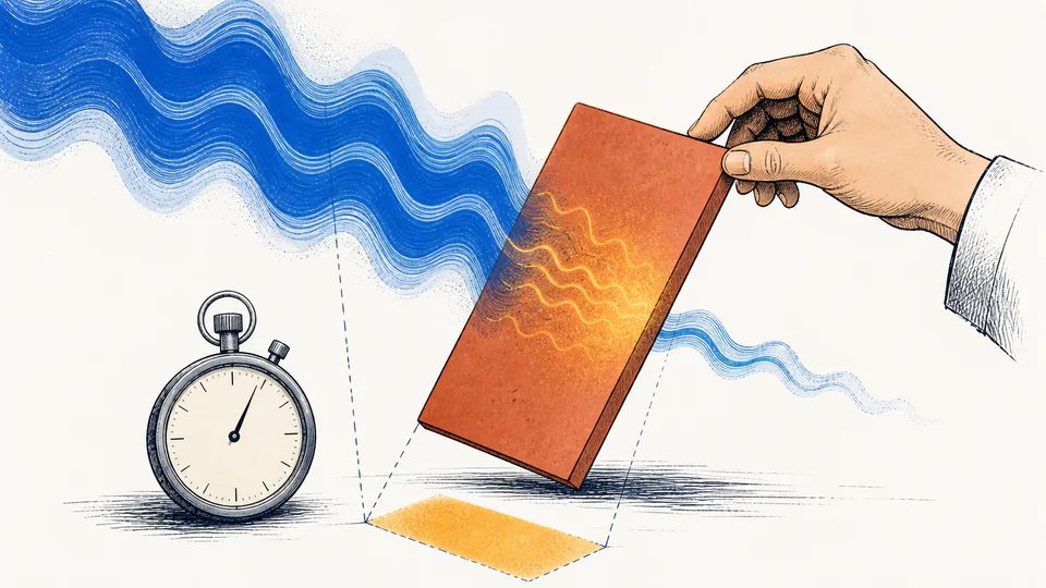
A 532 nm beam averages 100 W/m2 over 50 ms on a 0.02 m2 detector tilted 30 degrees. The energy ledger separates projected area from the detector absorption assumption.
Physics and electromagnetism
Calculate incident and absorbed electromagnetic energy on a tilted planar target over a finite exposure, with equivalent photon count at a selected wavelength.
Finite electromagnetic exposure
This page answers how much wave energy crosses a finite projected area and how much an idealized target absorbs. It does not infer irradiance from transmitter power or model reflection, scattering, heating, or tissue response.
Current model evidence
Trace geometry, power, time, absorption, and photon accounting without mixing their roles.
| Stage | Primary input | Secondary input | Intermediate value | Energy or relation |
|---|
DETAILED CALCULATION PROCESS
A_eff = A cos(theta); P_inc = I A_eff; U_abs = alpha I A cos(theta) t; E_gamma = h c/lambda; N = U_abs/E_gamma
Irradiance is defined on a plane normal to propagation. A cosine projection converts the physical target area to intercepted area, time converts power to energy, and the absorption fraction applies only after interception.
| Symbol | Meaning | Unit | Default basis |
|---|---|---|---|
| I | Time-averaged irradiance | W/m2 | 100 W/m2 |
| A | Physical planar area | m2 | 0.02 m2 |
| theta | Angle between propagation and surface normal | deg | 30 deg |
| t | Exposure duration | s | 50 ms = 0.05 s |
| alpha | Absorbed fraction | 1 | 0.80 |
| lambda | Vacuum wavelength | m | 532 nm |
| h, c | Planck constant and speed of light | J s; m/s | exact SI constants |
HOW TO USE THIS CALCULATOR
PHYSICS FOUNDATIONS FOR THIS MODEL
DEEP ANALYSIS 1
Tilting changes intercepted area. Changing alpha changes what the target retains. Applying both as one undocumented correction makes later review impossible.
DEEP ANALYSIS 2
For a vacuum plane wave, u_avg = I/c describes energy per volume in the propagating field. Deposited energy still requires area, time, and absorption.
DEEP ANALYSIS 3
Temperature change depends on mass, heat capacity, spatial distribution, conduction, and losses. This page stops at absorbed electromagnetic energy.
RESULT INTERPRETATION
A zero result at 90 degrees or zero absorption is a valid ideal boundary, not an input failure. In practice, beam divergence, edge illumination, roughness, and diffuse components may keep transfer above zero.
Use the photon count only when a narrow wavelength adequately represents the radiation. Broadband exposure requires integrating spectral irradiance rather than choosing one nominal wavelength.
REAL USE CASES
A 532 nm beam averages 100 W/m2 over 50 ms on a 0.02 m2 detector tilted 30 degrees. The energy ledger separates projected area from the detector absorption assumption.
A lab compares coupons at normal and grazing incidence. Equal measured irradiance does not imply equal intercepted energy, and a material-specific absorption fraction is still required.
EVIDENCE AND DATA QUALITY
Retain irradiance calibration and averaging method, illuminated-area drawing, angle reference, exposure timing, wavelength or spectrum, and the source of the absorption fraction. These are the inputs most likely to dominate uncertainty.
LIMITS AND EXCLUSIONS
TERMS USED HERE
RELIABLE SOURCES
FREQUENTLY ASKED QUESTIONS
The projected area is largest at normal incidence, so theta = 0 must give A_eff = A.
Yes. It represents an ideal fully reflecting or transmitting boundary and gives zero absorbed energy.
Only in the ideal planar, collimated-beam geometry. Edge area and diffuse radiation are excluded.
Not directly on this page. Convert a valid plane-wave field amplitude to average irradiance first.
No. Detection efficiency, collection losses, dead time, and noise belong in a photon-rate or detector model.
Not by itself. You also need mass, heat capacity, heat loss, and spatial deposition information.
IMPORTANT BOUNDARY
This is an idealized exposure-energy calculation, not a laser-safety classification, RF compliance assessment, detector calibration, or thermal hazard evaluation.