Warehouse sensor relocation
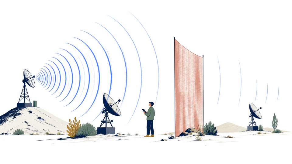
A 2.4 GHz sensor moves from 10 m clear line of sight to 100 m with a documented 6 dB obstruction allowance. The comparison isolates the distance penalty from the obstruction penalty.
Physics and electromagnetism
Compare received power for two far-field line-of-sight free-space radio scenarios using frequency, distance, antenna gains, and explicit additional losses.
Two-scenario electromagnetic link budget
This page compares two ideal far-field, matched-polarization line-of-sight links with the Friis relation expressed as a dB budget. Scenario means a concrete distance and added-loss case, not a generic score or probability.
Current model evidence
Keep free-space spreading and user-specified additional losses visible for both links.
| Scenario | Distance or ratio | FSPL or delta (dB) | Extra loss or delta (dB) | Received power or delta (dBm/dB) | Linear power or ratio |
|---|
DETAILED CALCULATION PROCESS
lambda = c/f; FSPL = 20 log10(4 pi r/lambda); P_r(dBm) = P_t(dBm) + G_t + G_r - FSPL - L_extra
The Friis free-space relation is evaluated in logarithmic form. Distance and wavelength determine FSPL, while antenna gains and explicitly entered non-free-space losses complete each link budget.
| Symbol | Meaning | Unit | Default basis |
|---|---|---|---|
| P_t | Power at transmit antenna input | W or dBm | 1 W = 30 dBm |
| f, lambda | Carrier frequency and vacuum wavelength | Hz; m | 2400 MHz |
| G_t, G_r | Directional antenna gains | dBi | 2 dBi each |
| r_A, r_B | Far-field path lengths | m | 10 m; 100 m |
| FSPL | Free-space path loss | dB | calculated separately |
| L_extra | Loss beyond free-space spreading | dB | 0 dB; 6 dB |
| P_r | Power at receive antenna output reference | dBm | calculated |
HOW TO USE THIS CALCULATOR
PHYSICS FOUNDATIONS FOR THIS MODEL
DEEP ANALYSIS 1
With frequency and other terms fixed, received power follows 1/r^2, so a distance ratio of ten produces a 100-fold power reduction.
DEEP ANALYSIS 2
At fixed dBi gains, higher frequency increases FSPL. At fixed physical apertures, gain may rise with frequency, changing the comparison.
DEEP ANALYSIS 3
Sensitivity, required SNR, noise bandwidth, modulation, interference, fading, availability target, and regulatory power limits remain separate decisions.
RESULT INTERPRETATION
A negative B-minus-A value means Scenario B receives less power. The ratio is always positive and is the linear counterpart of that dB change.
If both scenarios are identical, zero dB and a ratio of one are the correct boundary. Very short distances may violate far-field assumptions even though the formula returns a number.
REAL USE CASES
A 2.4 GHz sensor moves from 10 m clear line of sight to 100 m with a documented 6 dB obstruction allowance. The comparison isolates the distance penalty from the obstruction penalty.
Two proposed sites use the same radios and directional gains but different path lengths. The resulting received-power difference becomes one input to a separate fade-margin analysis.
EVIDENCE AND DATA QUALITY
Retain transmitter reference-plane power, cable-loss accounting, frequency, antenna models and orientations, gain patterns, polarization, path geometry, far-field justification, and the measurement or engineering basis for each additional loss.
LIMITS AND EXCLUSIONS
TERMS USED HERE
RELIABLE SOURCES
FREQUENTLY ASKED QUESTIONS
The equation holds antenna gains in dBi fixed; wavelength becomes shorter while geometric capture relative to isotropic changes.
No. Friis contains 1/r^2 and has no valid zero-distance link.
Include them in the appropriate extra-loss entry unless transmit power and received reference planes already exclude them.
Only through a defensible user-entered extra loss; the page does not predict obstruction loss.
No. Compare it with sensitivity and required SNR, then include fading, interference, and availability margin.
The calculated received powers are equal; this occurs for identical budgets or offsetting distance, gain, and loss changes.
IMPORTANT BOUNDARY
This ideal link comparison is not a coverage prediction, licensed-system design, interference study, compliance filing, or operational availability guarantee.