p

Physics and thermodynamics

Ideal Gas Trajectory Calculator

Project ideal-gas temperature and pressure through time in a closed rigid vessel under constant net heat rate and constant molar heat capacity.

Ideal gas thermal trajectory

Trace a rigid vessel through constant-rate heating or cooling

This trajectory couples a constant-volume energy balance to the ideal-gas state equation. It predicts a simple time history for a sealed, well-mixed gas—not a generic P-V graph.

Final temperature-
Final pressure-
Temperature rate-
Net energy added-

Current model evidence

Thermal trajectory checkpoints

The ledger samples one coupled energy-and-state trajectory at 0%, 25%, 50%, 75%, and 100%.
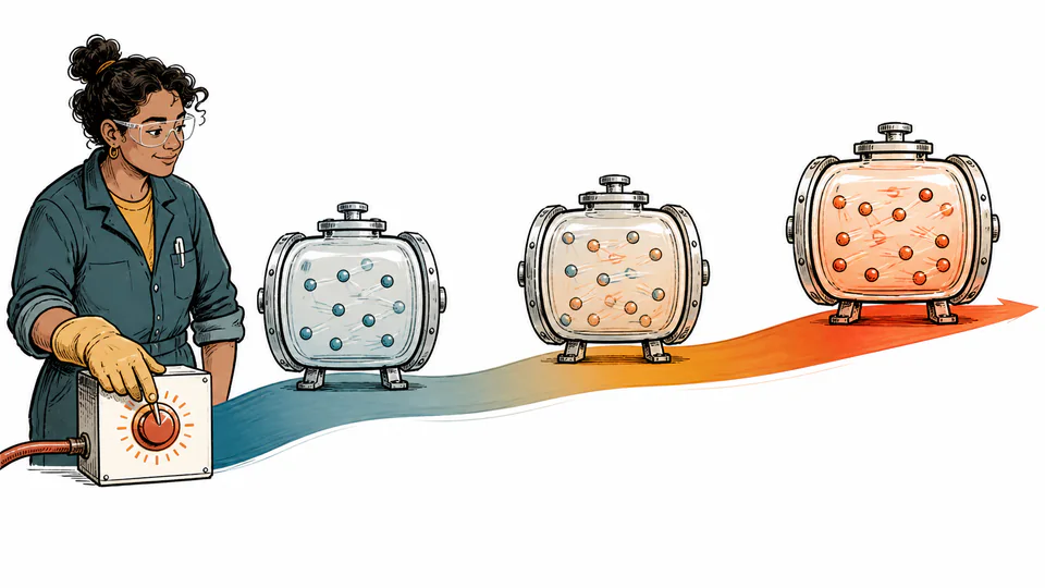
Editorial timeline of a sealed rigid gas vessel warming as measured energy enters over time
A fixed-volume gas translates net energy into temperature change, then into pressure change.
Temperature and pressure versus timeBoth traces come from the current constant heat-rate model; cooling reverses their direction.
Thermal trajectory checkpointsCurrent unrounded calculation path
The ledger samples one coupled energy-and-state trajectory at 0%, 25%, 50%, 75%, and 100%.
ProgressTime (s)Cumulative heat (J)Temperature (K)Pressure (kPa abs)Volume (m³)

DETAILED CALCULATION PROCESS

Formula, units, default substitution, and reconciliation

1. Governing relation

T0 = P0V/(nR); T(t) = T0 + Qdot t/(nCv); P(t) = nRT(t)/V

For a closed rigid vessel, boundary work is zero. With constant Cv and no mass flow, net heat changes internal energy by nCv Delta T.

2. Symbols and default basis

SymbolMeaningUnitDefault basis
P0Initial absolute pressurePa100 kPa
VRigid volume0.1
nSealed amountmol4
QdotConstant net heat rateW20
CvMolar constant-volume heat capacityJ/(mol K)20.8
tElapsed times0 to 300
T(t), P(t)Trajectory stateK, kPacalculated

3. Unit and sign normalization

  • Initial kPa is multiplied by 1000 when solving T0 in SI.
  • One watt is one joule per second, so Q = Qdot t.
  • A negative heat rate is allowed only while the modeled temperature stays above 0 K.

4. Current numerical substitution

    5. Independent reconciliation

    HOW TO USE THIS CALCULATOR

    Five steps from measurements to a defensible result

    1. Enter the sealed vessel free volume and gas amount.
    2. Enter initial absolute pressure; the model infers initial temperature from the state equation.
    3. Enter a signed net heat rate and a defensible constant Cv.
    4. Set the projection duration.
    5. Inspect the trajectory and the P/T ratio reconciliation before treating the envelope as plausible.

    IDEAL-GAS BASICS FOR THIS MODEL

    Concepts that control this specific decision

    Rigid boundary
    Fixed volume means no P dV boundary work.
    Closed system
    Gas amount remains constant throughout the trajectory.
    Heat capacity Cv
    Relates internal-energy change to temperature at constant volume.
    Coupled state
    Pressure follows temperature linearly when n and V are fixed.
    Net heat rate
    Already combines all heat gains and losses into one assumed constant value.

    DEEP ANALYSIS 1

    Wall heat capacity can dominate

    Real vessels store energy in metal, insulation, fixtures and contents. Ignoring them often makes predicted gas temperature change too fast.

    DEEP ANALYSIS 2

    Cv can vary with temperature

    The constant value is a local approximation; large thermal spans need temperature-dependent property data.

    DEEP ANALYSIS 3

    Uniform temperature is demanding

    Rapid heating can create gradients, so a single gas temperature and pressure trace may not represent local hot spots.

    RESULT INTERPRETATION

    What the current output does—and does not—decide

    Positive heat produces linear temperature and pressure rises in this simplified model. Negative heat produces linear decreases until the absolute-zero guard is reached.

    The pressure rate is a consequence of the thermal model, not a permitted vessel heating rate or relief-system assessment.

    REAL USE CASES

    Two decisions with different boundary conditions

    Bench vessel warm-up

    A sealed 0.1 m³ vessel containing four moles receives a measured net 20 W for five minutes. The checkpoints estimate the idealized pressure rise.

    Cooling feasibility screen

    A cold-stage plan enters a negative heat rate. If the endpoint crosses 0 K, the input is rejected; before that, the result remains only a simplified thermal envelope.

    EVIDENCE AND DATA QUALITY

    What to retain with the exported result

    Retain vessel free volume, amount-loading method, initial pressure calibration, heat-input measurement, wall and fixture inventory, selected Cv source, ambient conditions, and time records.

    LIMITS AND EXCLUSIONS

    Where the model stops

    • Closed, rigid, spatially uniform ideal-gas vessel only.
    • Net heat rate and molar Cv are constant.
    • Vessel walls, fittings, contents and external thermal resistance are excluded.
    • No mass flow, reaction, phase change, radiation nonlinearity, or real-gas factor is modeled.
    • Not a pressure-vessel allowable-rate or relief sizing calculation.

    TERMS USED HERE

    Six terms that keep the calculation unambiguous

    Trajectory
    State values indexed by elapsed time.
    Net heat rate
    Algebraic heat entering the modeled gas per second.
    Cv
    Molar heat capacity at constant volume.
    Internal energy
    Microscopic energy changed by heat in this rigid model.
    Thermal gradient
    Spatial temperature difference excluded by the uniform-state assumption.
    Rigid vessel
    Control volume whose boundary does not change volume.

    RELIABLE SOURCES

    References supporting the equation and units

    FREQUENTLY ASKED QUESTIONS

    Questions specific to this calculation

    Why is initial temperature inferred?

    P0, V and n already define T0 under the ideal-gas equation.

    Can heat rate be negative?

    Yes, for cooling, provided the modeled endpoint remains above 0 K.

    Why are pressure and temperature lines proportional?

    With n and V fixed, P/T = nR/V is constant.

    Does the model include vessel-wall heating?

    No. Add wall and hardware heat capacities in a fuller energy model.

    Which Cv should I use?

    Use a source appropriate to the gas composition and temperature range; 20.8 J/(mol K) is close to a monatomic ideal-gas value, not universal.

    Can this determine a safe pressure ramp?

    No. Safety requires vessel ratings, controls, heat-transfer details and applicable codes.

    IMPORTANT BOUNDARY

    Use the result as analysis, not certification

    This idealized thermal projection is not a pressure-vessel design, hazard analysis, control law, or operating limit.