Physics and mechanics
Lens Solver Calculator
Solve focal length, object distance, or image distance with the thin-lens equation, then determine magnification, image height, orientation, and real or virtual image status.
CURRENT MODEL
Choose the unknown and enter the other lens conjugates
Physics students, camera and projection technicians, and optics educators checking first-order image geometry before detailed ray tracing.
Decision supportedResolve one missing thin-lens conjugate and classify the resulting image using an explicit real-object-positive sign convention.
LIVE THIN-LENS GEOMETRY
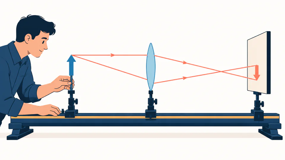
Principal-ray image construction
The live diagram places the object and image on the declared sign-convention axis and switches to a collimated state when a conjugate lies at infinity.
| Quantity | Symbol or equation | Current value | Unit |
|---|
How to use
Solve one conjugate under one sign convention
- Select image distance, object distance, or focal length as the single unknown.
- Enter positive object distance for a real object on the incoming-light side.
- Enter positive image distance for a real image or negative distance for a virtual image.
- Use positive focal length for a converging lens and negative focal length for a diverging lens.
- Enter signed object height, then inspect magnification sign and image classification together.
- Check the reciprocal residual; treat a reported infinity state as collimated geometry, not a failed calculation.
Thin-lens fundamentals
Six rules that prevent sign errors
- Conjugate pair
- Object and image planes are linked through one focal length by reciprocal distances.
- Real object
- Incoming rays diverge from the object and use positive object distance in this convention.
- Real image
- Outgoing rays physically converge, giving positive image distance and possible screen capture.
- Virtual image
- Outgoing rays diverge as if from a point on the object side, giving negative image distance.
- Magnification sign
- Negative transverse magnification means inversion; magnitude states enlargement or reduction.
- Focal-plane boundary
- An object at the converging lens focal plane produces parallel output and an image at infinity.
Calculation method
Rearrange reciprocal distances before classifying the image
The selected field is removed from input. The model rearranges 1/f = 1/do + 1/di and detects a near-zero reciprocal denominator before division. This produces an explicit collimated state instead of a misleading huge number.
For finite conjugates, m = -di/do scales the signed object height. The signs of di and m establish real or virtual and upright or inverted; the absolute magnification distinguishes enlarged, reduced, or same-size.
Principal-plane reference
Thin-lens distance begins at the ideal principal plane. Measuring from a lens rim or housing introduces systematic focus error.
Paraxial condition
The equation assumes small ray angles and height. Fast lenses and large off-axis fields need aberration-aware ray tracing.
Virtual-object extension
Negative object distance can represent converging incident rays, but users must maintain the same sign convention across a multi-element system.
Uncertainty near focus
When do approaches f, small distance or focal-length errors create very large image-distance uncertainty even if the nominal equation is exact.
Detailed calculation process
Symbols, current substitution, intermediate quantities, and reconciliation
1/f = 1/d_o + 1/d_i; m = -d_i/d_o; h_i = m h_oReciprocal distances and magnification retain full precision. Classification uses unrounded signs and magnitude before values are formatted.
| Symbol | Meaning | Default | Unit |
|---|---|---|---|
| d_o | Object distance from principal plane | 30 | cm |
| d_i | Image distance from principal plane | solved | cm |
| f | Paraxial focal length | 10 | cm |
| h_o | Signed object height | 5 | cm |
| m | Transverse magnification | calculated | dimensionless |
| h_i | Signed image height | calculated | cm |
Waiting for valid inputs.
Interpretation
Read signs, screen behavior, and scale together
A positive image distance identifies a real image that can be intercepted by a screen; its negative magnification means inversion for a real object and converging lens. A negative image distance indicates a virtual image. Infinity identifies a parallel-ray boundary where finite magnification is not reported.
Evidence and measurement
Keep the reference plane with every distance
Record lens part and orientation, wavelength, effective focal-length source, principal-plane location or thin-lens assumption, object and screen datum, focus criterion, object height, aperture, and environmental conditions. Preserve measurement uncertainty and whether distances were signed or unsigned.
Scope and limitations
What the thin-lens solver does not certify
- Lens thickness, separated elements, or principal-plane offsets
- Spherical, chromatic, coma, astigmatism, or distortion effects
- Diffraction-limited spot size, depth of field, or modulation transfer
- Mechanical focus tolerance, housing datum error, or thermal drift
- Vignetting, clear-aperture clipping, or off-axis chief rays
- Laser exposure or optical assembly safety
One thin paraxial lens in the same medium on both sides, a real object by default, negligible lens thickness, small ray angles, and distances measured from the principal plane. Positive focal length denotes a converging lens.
Key terminology
Image-formation glossary
- Focal length
- Paraxial distance linking incoming parallel rays to the focal point.
- Conjugate planes
- Object and image planes connected by the lens mapping.
- Principal plane
- Effective reference plane from which first-order distances are measured.
- Real image
- Plane where physical rays converge and can illuminate a screen.
- Virtual image
- Apparent source point found by extending diverging rays backward.
- Magnification
- Signed image-height to object-height ratio, equal here to -di/do.
- Diopter
- Reciprocal metre measure of optical power.
- Paraxial ray
- Ray close enough to the axis for small-angle first-order optics.
Practical cases
Two image problems with different boundaries
Projection-screen placement
A 10 cm converging lens views a 5 cm object 30 cm away. The solver places the real image at 15 cm with -0.5 magnification, giving a 2.5 cm inverted image for a first bench setup.
Collimator setup
Placing the object at the focal plane makes the ideal image distance infinite. The output warns the technician to assess angular collimation rather than search for a finite screen location.
Important note
First-order focus is not image-quality acceptance
Use the conjugate solution to establish nominal geometry. Preserve signed distances and obtain detailed optical tolerancing before committing camera, projection, metrology, or high-power hardware.
Frequently asked questions
Which sign convention does the solver use?
It uses 1/f = 1/do + 1/di with positive do for a real object, positive di for a real image, and positive f for a converging lens. A virtual image has negative di.
What happens when the object is at the focal plane?
The denominator used to solve image distance is zero. The ideal paraxial output is collimated, so the page reports image at infinity instead of an enormous or nonfinite number.
Why is a real image inverted?
With the declared sign convention, a positive image distance and positive object distance make m = -di/do negative, so the transverse image height has the opposite sign.
Can this model solve a thick compound lens?
Not directly. Thick or multi-element systems require principal planes or an ABCD-matrix model; entering an effective focal length is only a first-order approximation.
Does object height affect image distance?
No in paraxial first-order optics. Height scales image height through magnification but does not change the conjugate distances.
Why might a measured focus differ?
Lens thickness, wavelength-dependent focal length, spherical aberration, object depth, assembly spacing, and locating distance from the wrong reference plane can all shift the measured focus.
Authority and follow-on work
Reliable sources and related calculators
- OpenStax College Physics — Image Formation by LensesSupports the thin-lens equation, magnification, ray construction, and real or virtual image interpretation.
- OpenStax Physics — Key EquationsLists thin-lens and magnification relations with sign conventions.
- NIST Guide to the SISupports SI length conversion and the reciprocal-metre diopter.
Related calculators
Continue with a distinct optics question without silently changing the model boundary.