Physics and mechanics
Lens Trajectory Calculator
Trace one signed paraxial ray through free space, an ideal thin lens, and an observation plane using ABCD matrices, including aperture clearance and axis crossing.
CURRENT MODEL
Enter the declared physical case
Optics students and bench engineers checking first-order ray height, slope, clearance, and observation-plane placement.
Decision supportedDetermine whether a declared ray clears the lens and where it travels after refraction before using a full multi-element or aberration model.
LIVE PHYSICAL ANALYSIS
Piecewise ray height across the optical bench
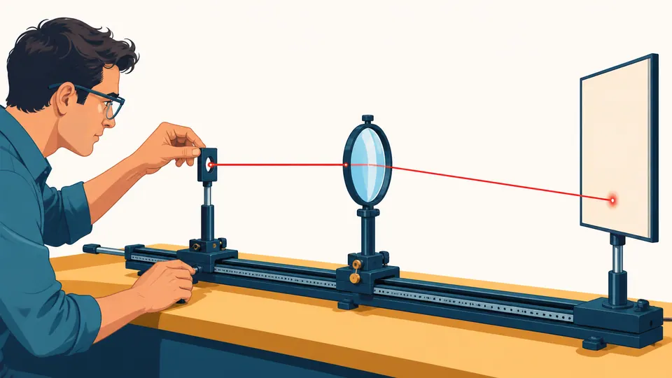
The live optical-axis plot shows the incoming segment, lens deflection, clear aperture, observation plane, and any axis crossing.
| Plane | Axial position (mm) | Ray height (mm) | Ray angle (mrad) | State |
|---|
How to use
Propagate one declared ray through the lens plane
- Set signed input height and small input angle at a named reference plane.
- Enter the free-space distance from that plane to the thin lens.
- Enter signed focal length and the actual clear-aperture diameter.
- Set the lens-to-observation-plane distance.
- Inspect aperture clearance before trusting downstream height or crossing.
- Use the determinant and sequential-versus-matrix residual as independent checks.
Trajectory fundamentals
Five parts of an ABCD ray state
- Ray height
- Signed transverse distance from the optical axis at a named plane.
- Ray angle
- Signed paraxial slope in radians, not a field-of-view label.
- Translation matrix
- Free space changes height by distance times angle while preserving angle.
- Thin-lens matrix
- The ideal lens preserves height and changes slope by -y/f.
- Aperture clearance
- Clear radius minus absolute lens-plane ray height; zero is the physical edge.
Calculation method
Translate, refract, then translate again
The model converts millimetres to metres and milliradians to radians, propagates to the lens, applies the thin-lens slope change, and propagates to the observation plane.
A separate multiplied ABCD matrix reproduces the final height and angle. The visual answers where the ray travels; the ledger records exact plane states and the aperture decision.
Matrix order matters
Ray matrices multiply in physical encounter order from right to left. Reversing a lens and translation changes both system B and D terms.
Axis crossing is conditional
-y/theta is meaningful only when outgoing angle is nonzero; a negative result places the crossing upstream of the lens.
Paraxial screening
The 0.1 rad message is only a visibility warning. High numerical aperture, large field height, or precision design needs exact refraction and aberration analysis.
Detailed calculation process
Symbols, current substitution, intermediate quantities, and reconciliation
[y_S;theta_S]=P(L2)L(f)P(L1)[y0;theta0]ABCD propagation uses metres and radians at full precision; displayed mm and mrad are derived afterward.
| Symbol | Meaning | Default | Unit |
|---|---|---|---|
| y0 | Input ray height | 5 | mm |
| theta0 | Input ray angle | 0 | mrad |
| L1 | Distance before lens | 100 | mm |
| f | Signed focal length | 50 | mm |
| L2 | Distance after lens | 100 | mm |
| D | Clear aperture diameter | 30 | mm |
Waiting for valid inputs.
Evidence to retain
Anchor every ray to a real plane
Record coordinate origin, axis direction, ray-height and angle sign, medium index, lens principal plane and focal length, aperture stop, element centering, propagation distances, wavelength, measurement uncertainty, and whether the traced ray represents a marginal, chief, or test ray.
Scope and limitations
Where the one-ray trace stops
- No thick-lens surfaces, multiple elements, index changes, mirrors, or decentration
- No diffraction, interference, polarization, or wavefront propagation
- No spherical/chromatic aberration, distortion, coma, or astigmatism
- No stop before the lens or post-lens mechanical obstruction
- No finite beam diameter or bundle envelope
- No universal accuracy guarantee from the paraxial angle guide
One centered ideal thin lens in a homogeneous medium, small paraxial angles, free-space segments, and no diffraction, aberration, decentration, or thick-lens principal-plane shift.
Key terminology
Ray-matrix glossary
- Ray vector
- The ordered pair of transverse height and paraxial angle.
- ABCD matrix
- A two-by-two first-order transform for an optical segment or system.
- Chief ray
- A field-defining ray passing through the aperture stop centre.
- Marginal ray
- A ray near the aperture edge used to represent bundle extent.
- Axis crossing
- The signed downstream distance where the extrapolated ray height becomes zero.
- Matrix determinant
- A first-order invariant equal to one for this same-medium lossless system.
Practical cases
Two ray checks with different outcomes
Bench alignment ray
A 5 mm parallel input reaches a 50 mm lens, bends by -100 mrad, crosses the axis 50 mm later, and reaches -5 mm at the 100 mm observation screen.
Aperture-edge qualification
A tilted input reaches exactly the declared clear radius and remains valid with zero clearance. A slightly smaller aperture triggers an error rather than drawing a blocked downstream ray.
Important note
One paraxial ray does not describe image quality
Use a ray bundle, exact surface prescription, stop model, wavelength data, and wave-optics analysis when resolution, spot size, aberration, vignetting, or high numerical aperture matters.
Frequently asked questions
What does trajectory mean for a lens ray?
It is the piecewise paraxial ray height and slope through free space and the thin-lens plane, not the physical orbit of a photon.
Why does ray height not jump inside the thin lens?
An ideal zero-thickness lens changes slope at one plane while preserving transverse height; a thick lens needs two surfaces and internal propagation.
What does a negative observation height mean?
The ray crossed the optical axis and lies on the opposite signed side at the observation plane.
Why reject a ray outside the aperture?
Once blocked, a downstream geometric ray would be misleading. Diffraction around the stop is a different wave-optics problem.
Is 0.1 rad a universal paraxial limit?
No. It is a visible screening guide, not a standard. Required accuracy, lens shape, field height, and aberrations determine whether a smaller angle is necessary.
Can this trace multiple lenses?
Not on this page. Multiply additional element and translation matrices in physical order, while preserving indices and principal planes.
Authority and follow-on work
Reliable sources and related calculators
- MIT 6.161 Geometric Optics NotesABCD ray vectors, free-space propagation, and thin-lens matrix.
- OpenStax College Physics - Image Formation by LensesParaxial lens and ray-tracing context.
- NIST SI Unit RulesLength and angular-unit presentation.
Related calculators
Continue with a distinct physical question without silently changing this page's model boundary.