Physics and engineering
Mirror Trajectory Calculator
Trace an off-axis ray to an exact spherical mirror hit, reflect it with vector geometry, and compare its axis intercept with the paraxial image prediction.
CURRENT MODEL
Place the object and choose one spherical surface hit
Optics learners, bench technicians, and telescope builders checking where a selected marginal ray travels rather than assuming every ray meets the paraxial focus.
Decision supportedJudge whether a chosen ray height remains close enough to the paraxial image prediction for an initial mirror layout.
LIVE VECTOR REFLECTION
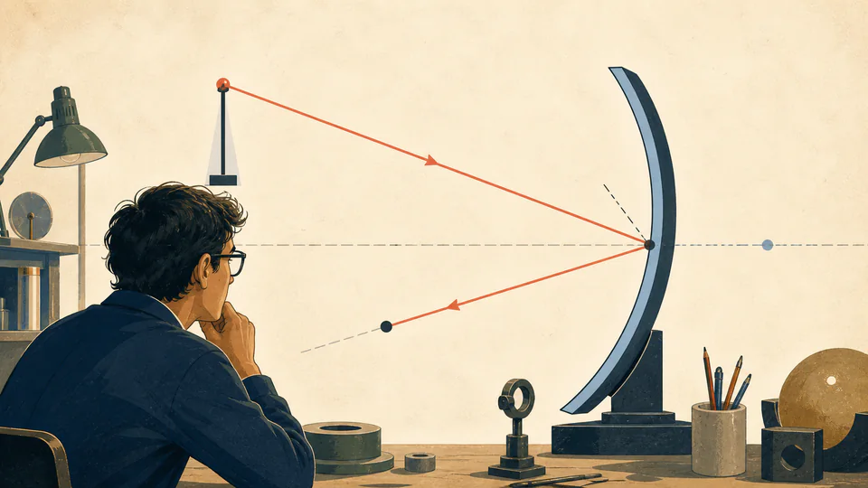
Exact reflected-ray path
The live diagram uses the current source point and surface hit. It does not substitute decorative rays or a fixed focal sketch.
| Quantity | Symbol or equation | Current value | Unit |
|---|
How to use
Trace one physical ray before judging a focus
- Select concave or convex so the spherical centre is placed on the correct side of the vertex.
- Enter a positive radius magnitude and real-object distance measured from the vertex.
- Set the signed object height that defines the ray source above or below the axis.
- Choose a signed surface hit height strictly inside the sphere radius.
- Compare the exact reflected-axis intercept with the paraxial image distance and inspect the difference.
- Use the reflection residual as a numerical check, then retain geometry and sign convention with the result.
Ray-trajectory fundamentals
Six geometric facts determine the reflected line
- Sphere intersection
- The hit x-coordinate follows the circle, not a flat vertex plane.
- Local normal
- The radius from centre of curvature to hit point defines the reflecting normal.
- Incident direction
- Object and hit coordinates establish a normalized incoming vector.
- Specular reflection
- Only the normal vector component reverses; tangential direction is retained.
- Axis intercept
- The reflected parametric line may cross in front, behind, or never at finite distance.
- Paraxial comparator
- The mirror equation describes near-axis first-order behaviour, not this exact marginal ray.
Calculation method
Intersect, normalize, reflect, and only then find an image intercept
The circle equation locates the physical surface point at the selected height. Unit incident and normal vectors avoid mixing path length with direction. The vector reflection identity reverses twice the incident projection onto the normal.
The exact reflected line is extended to y=0 to find its signed axis intercept. Separately, f=R/2 and the mirror equation produce the paraxial image distance. Their longitudinal difference measures this ray's departure, not a complete spot size.
Spherical aberration signal
Repeating the calculation at multiple ray heights reveals longitudinal spherical aberration, but one ray cannot quantify a full wavefront or encircled energy.
Convex virtual intercept
A convex mirror sends rays back diverging. Their backward extension can cross behind the surface even though no physical light travels there.
Coordinate sensitivity
Near a reflected direction parallel to the axis, a tiny angular perturbation creates a very large intercept shift. Report direction uncertainty as well as distance.
Detailed calculation process
Symbols, current substitution, intermediate quantities, and reconciliation
v_out = v_in - 2(v_in dot n)n; x_axis = x_h - y_h v_out,x/v_out,ySphere intersection, unit vectors, and line intersection retain full precision. The reflection-law residual is computed before formatting.
| Symbol | Meaning | Default | Unit |
|---|---|---|---|
| R | Sphere radius magnitude | 200 | mm |
| d_o | Real-object distance | 300 | mm |
| h_o | Object transverse height | 20 | mm |
| y_h | Selected hit height | 30 | mm |
| n | Unit surface normal | calculated | dimensionless |
| v_out | Unit reflected direction | calculated | dimensionless |
Waiting for valid inputs.
Interpretation
Read the exact intercept as one ray, not an image guarantee
A positive exact image distance means the reflected ray crosses the axis in front of the mirror; a negative value identifies a virtual backward intercept. The difference from the paraxial distance grows as the selected ray samples more strongly curved surface regions.
Evidence and measurement
Retain enough geometry to reproduce the ray
Save mirror type, radius and tolerance, vertex location, object datum and height, selected hit coordinate, surface clear aperture, coordinate handedness, wavelength, coating side, alignment uncertainty, and whether the measured surface departs from a best-fit sphere.
Scope and limitations
What one two-dimensional ray cannot establish
- Diffraction, phase, polarization, interference, or beam waist
- Three-dimensional skew rays or off-axis field bundles
- Surface figure errors, roughness, coating penetration, or scatter
- Finite aperture clipping or mount obscuration outside the chosen hit
- Image spot, wavefront error, modulation transfer, or encircled energy
- Alignment tolerance or eye and laser safety
Two-dimensional geometric optics, a spherical mirror with vertex at x=0, object on the incoming x<0 side, specular reflection, and no diffraction or coating phase shift.
Key terminology
Ray-tracing glossary
- Incident ray
- Directed line arriving at the mirror surface.
- Surface normal
- Perpendicular direction at the exact hit point.
- Specular reflection
- Reflection with equal incident and reflected angles about the normal.
- Axis intercept
- Point where a traced line crosses the optical axis.
- Marginal ray
- Ray sampling a higher part of the clear aperture.
- Longitudinal aberration
- Axial separation between ray intercepts or a reference focus.
Practical cases
Two ray questions the paraxial equation alone cannot answer
Fast concave mirror
The default 30 mm-high ray crosses at 111.697654 mm while the paraxial prediction is 150 mm. That gap warns against using the first-order focus as a marginal-ray acceptance point.
Convex sensor mirror
A designer traces an edge ray to see where its virtual extension appears behind a convex surface, then checks whether the angular spread fits the downstream sensor field.
Important note
A ray intercept is not a qualified optical design
Use this exact geometry as a diagnostic and teaching result. Real hardware needs a ray bundle, toleranced surfaces, coating data, aperture analysis, and independent optical verification.
Frequently asked questions
How is this different from the mirror equation?
The mirror equation is paraxial. This page intersects a chosen ray with the actual circle, reflects its vector about the local normal, and only then compares with the paraxial result.
What does a negative exact image distance mean?
With this page's convention, positive distance lies in front of the mirror. A negative value means the reflected ray extension crosses behind the mirror, a virtual intercept.
Why do high rays miss the paraxial focus?
The spherical surface normal changes nonlinearly with height. Marginal rays therefore cross the axis at different longitudinal positions, the basis of spherical aberration.
Does the ray represent a finite beam?
No. It is one geometric ray selected by a source point and surface hit. Beam width, diffraction, and intensity require another model.
Can the reflected ray be parallel to the axis?
Yes for particular source and hit geometry. The page reports no finite axis intercept rather than serializing Infinity.
Can this predict an off-axis image spot?
Not by itself. A spot requires tracing a bundle of rays in two transverse dimensions and including aperture, field angle, and surface errors.
Authority and follow-on work
Reliable sources and related calculators
- OpenStax University Physics — Spherical MirrorsSupports the law of reflection, spherical geometry, and paraxial limitations.
- OpenStax University Physics — Optics Key EquationsProvides the paraxial mirror equation used only as a comparator.
- NIST Guide to the SISupports the millimetre-to-metre conventions recorded with bench geometry.
Related calculators
Continue with a distinct physics question without silently changing the model boundary.