Uniform straight low-pressure run
Project-specific skin weights can support a useful preliminary line-load record before hardware and structure design.
Home & Construction
Keep distributed dead load separate from point equipment loads and report demand only; no hanger, anchor, trapeze, structure, or seismic resistance is invented.
SUSPENDED DUCT DEMAND
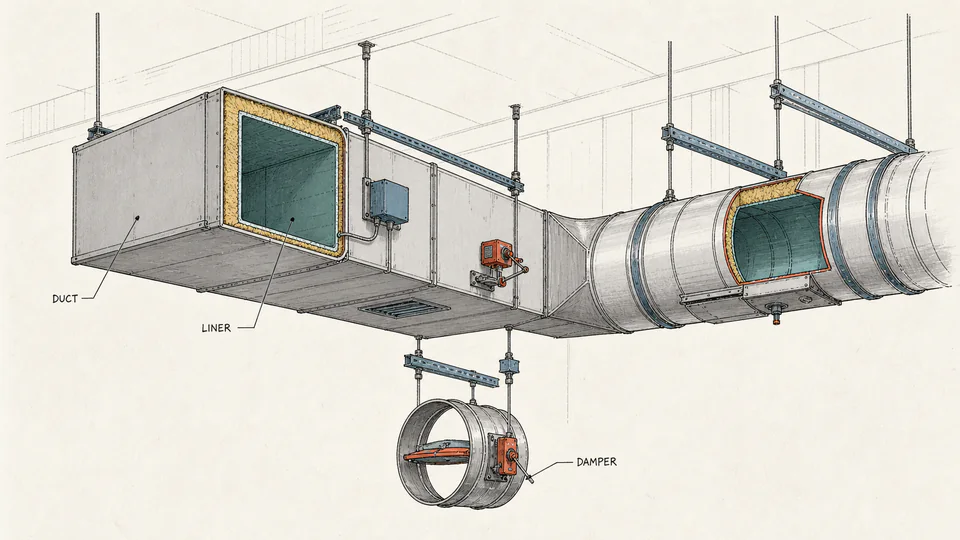
Sheet, insulation, liner, and distributed accessories form a line load. A planning factor and hanger spacing create span demand; point loads remain separate.
SUBJECT DECISION ILLUSTRATION
The illustration explains the professional setting without pretending to be a data chart. The ledger below preserves the entered values and calculation path.
| Load component | Area / length basis | Weight / factor | Component demand | Line / support result | Boundary |
|---|
How to use
Suspended-load fundamentals
Calculation method
Area-based weights multiply the entered duct skin area. Distributed accessories are added before dividing by centerline length. The planning factor applies to this line load. Hanger spacing creates an interior distributed-span screen, while the point load remains separate and is added only to the aggregate planning demand.
Weight boundary
Gauge, material, reinforcement, joints, stiffeners, liner, insulation, facing, sealant, and accessories determine actual weight. Use a project or manufacturer schedule rather than a generic universal value.
Reaction boundary
Ends, unequal spacing, fittings, offsets, risers, branches, dampers, access doors, flexible connections, equipment, and support stiffness change reactions. Preserve locations for design.
Pressure and seismic boundary
Internal pressure, collapse, vibration, fan thrust, thermal movement, seismic restraint, impact, maintenance loads, and fire/smoke system actions require separate construction and support checks.
Detailed calculation process
The current cards and component ledger provide the live reconciliation.
Result interpretation
Use line and point-load records to coordinate hangers and supporting structure. Do not label the result safe, allowable, or compliant without defining hardware, anchors, trapeze geometry, structure, load combinations, and the governing standard.
Decision analysis
Heavy dampers, access doors, coils, fans, silencers, and equipment connections should not be smeared across the run when local reactions matter. Provide independent support when required by the design.
Evidence and data lineage
Keep model/drawing revision, duct section and route, material, gauge, reinforcement, joints, liner and insulation product weights, accessory and point-load schedule, hanger spacing and layout, planning-factor basis, seismic category, anchor and structure references, designer, date, and unrounded demand export.
Limits and exclusions
Key terminology
Worked decision cases
Project-specific skin weights can support a useful preliminary line-load record before hardware and structure design.
Concentrated components, reinforcement, vibration, and connection forces require localized supports and cannot rely on an average hanger value.
Authoritative basis
This page calculates entered dead-load demand only. Qualified mechanical, seismic, and structural design must establish real support spacing, hardware, anchors, structure, load combinations, and compliance.
Sheet, liner, and insulation mass generally scale with duct skin area.
No. It remains separate so its actual support location can be reviewed.
No. It is an entered demand multiplier and cannot replace governing load combinations.
A straight sequence of spans normally has support points at both ends.
No. Spacing is an input that must be justified by the approved system and design.
Pressure affects construction and can create forces not represented by this dead-load model.