Straight wall with full pallets
Rectangular geometry aligns closely with unit dimensions and five full pallets. Caps and aggregate still retain separate package and volume bases.
Home & Construction
Round face units, caps, pallets, aggregate, and geogrid independently so one generic waste factor does not distort every material family.
RETAINING WALL MATERIAL TAKEOFF
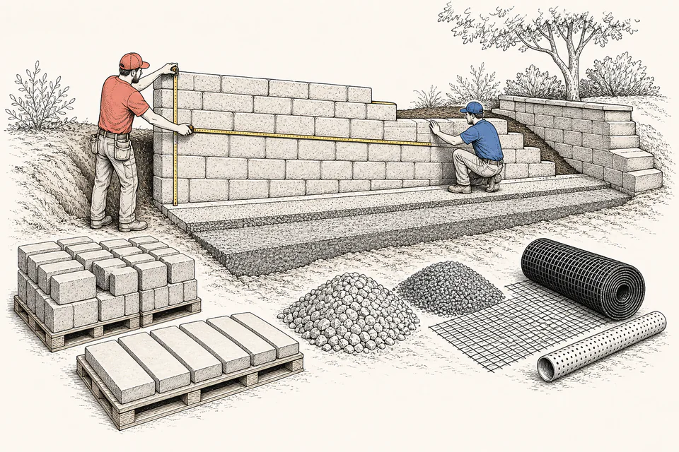
Face geometry establishes columns and courses before block allowance and pallet rounding. Caps, compacted base, drainage stone, and geogrid retain distinct dimensions and quantities.
PROJECT DECISION ILLUSTRATION
Translate exposed and buried wall geometry into the selected block module, course count, caps, and allowance; the ledger retains unrounded demand before package decisions.
| Material family | Measured basis | Allowance / package | Unrounded demand | Order quantity | Residual / field note |
|---|
How to use
Material takeoff fundamentals
Calculation method
Wall length and height are independently divided by unit face dimensions and rounded up to whole columns and courses. Their product receives one block allowance and rounds to whole blocks, then pallets. Caps follow their own length and package basis. Aggregate remains cubic yards and geogrid remains square feet.
Curves, corners, and batter
Curves change effective face length, corners require special units or cuts, and batter shifts course alignment. Steps, columns, returns, radii, bond pattern, unit setback, and proprietary details need a course-by-course drawing or supplier takeoff.
Compacted versus delivered volume
Base and drainage results represent modeled in-place geometric volume. Moisture, density, compaction, bulking, contamination, minimum delivery, stockpile loss, core fill, and supplier sales units can change delivered tons or cubic yards.
Reinforcement boundary
The calculator multiplies entered layers and depth by wall length. Only the responsible designer and proprietary system requirements can establish grid type, strength, orientation, splice, coverage, elevations, embedment, connection, and termination.
Detailed calculation process
The current result cards and ledger above provide the final reconciliation.
Result interpretation
Block and cap results include the entered rectangular geometry and package rounding. Base, drainage, and geogrid use the entered section only. None of the outputs establishes design adequacy, delivered mass, special-unit demand, or complete drainage scope.
Decision analysis
A change in wall height can add a full course, alter reinforcement, and change drainage or excavation. A curve or corner can change special-unit and cut demand without much area change. Freeze the approved revision before converting the takeoff to purchase orders.
Evidence and data lineage
Keep survey and wall stations, plan and profile revision, total and exposed heights, buried courses, block and cap product and dimensions, bond and setback, curve and corner drawings, blocks and caps per pallet, allowance rationale, base and drainage section, pipe and outlet, filter fabric, core fill, geogrid type, layer elevations and embedment, supplier sales units, density conversions, delivery plan, estimator, and exact unrounded results.
Limits and exclusions
Key terminology
Worked decision cases
Rectangular geometry aligns closely with unit dimensions and five full pallets. Caps and aggregate still retain separate package and volume bases.
Area may be similar, but radius cuts, special units, step-down courses, extra caps, and offcuts require a course drawing and product-specific supplier takeoff.
Professional basis
Release material only from the approved engineered wall design, current manufacturer details, verified field dimensions, supplier package data, and contractor logistics plan. The calculator is not a wall design tool.
The wall must be assembled from whole units in both directions before a reserve is added.
Only if you enter them; use the approved design height represented by the material takeoff.
Not safely. Convert in-place geometry to supplier units using density, compaction, moisture, and delivery factors.
Caps use their own face length and package quantity and may be a different product family.
No. It only extends entered layers and depth; engineering determines type, spacing, strength, and connection.
Only as rough face geometry. Curves and corners need a product-specific course layout and special-unit takeoff.