Drained level landscape wall
Project geotechnical values and level backfill support a preliminary active-pressure record. The engineer still evaluates the proprietary wall system and all stability modes.
Home & Construction
Report destabilizing lateral loads and their resultant only; stability, reinforcement, drainage, and capacity remain outside the model.
RETAINING WALL LATERAL LOAD
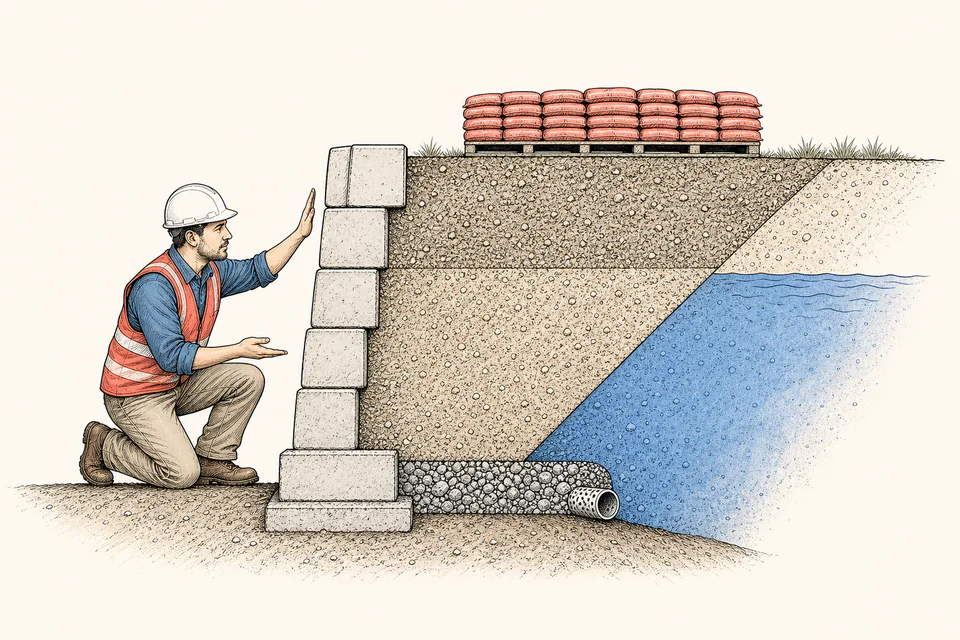
A simplified Rankine coefficient converts entered level-backfill soil properties into active force. Uniform surcharge and water are kept separate; wall resistance and stability are intentionally outside the result.
PROJECT DECISION ILLUSTRATION
Keep triangular soil pressure, uniform surcharge, and hydrostatic pressure as distinct load components; the ledger reconciles their forces, moment arms, and combined resultant.
| Pressure component | Input basis | Distribution | Force per wall ft | Moment arm | Moment per wall ft |
|---|
How to use
Lateral-load fundamentals
Calculation method
The Rankine active coefficient uses the entered drained friction angle. Soil pressure grows linearly with depth, so its resultant is triangular. A uniform surcharge creates rectangular lateral pressure. Water pressure is triangular over the entered water height. Forces and moments are summed per wall foot before multiplying force by wall length.
Model validity
The simplified coefficient assumes level cohesionless backfill, a vertical smooth wall interface, drained properties, and active movement. Sloping grade, wall batter, wall friction, cohesion, layered soil, compaction stress, at-rest behavior, passive resistance, and constrained movement require another model.
Water boundary
Water can dominate lateral force and destabilize retained soil. The input exposes the magnitude of an entered water column but does not design drains, outlets, filters, surface diversion, erosion control, seepage, uplift, or drawdown.
Capacity boundary
Wall and reinforced-soil geometry, unit weight, interfaces, connection strength, grid properties, foundation soil, toe embedment, groundwater, slopes, and external loads determine resistance. This page intentionally reports no factor of safety, utilization, pass, or allowable height.
Detailed calculation process
The current result cards and ledger above provide the final reconciliation.
Result interpretation
The result quantifies only the declared simplified lateral components. A larger retained height increases soil force with the square of height. The page does not calculate wall weight, grid resistance, foundation bearing, sliding, overturning, internal, facial, compound, global, or seismic stability.
Decision analysis
If backfill slopes, groundwater varies, surcharge is localized, soil is layered or cohesive, the wall cannot move to active state, or seismic loading matters, stop using the simplified model. Qualified geotechnical and structural design should select the governing method and combinations.
Evidence and data lineage
Keep survey, wall station and section, total design height, exposed and buried geometry, backfill slope, soil boring and laboratory data, drained unit weight and friction angle, groundwater observations and design level, drainage plan, surcharge magnitude and footprint, adjacent foundations, compaction method, seismic parameters, design method, responsible professionals, calculation revision, and exact unrounded loads and moments.
Limits and exclusions
Key terminology
Worked decision cases
Project geotechnical values and level backfill support a preliminary active-pressure record. The engineer still evaluates the proprietary wall system and all stability modes.
A localized vehicle load and water accumulation violate the uniform drained assumptions. The page can illustrate components, but a project-specific surcharge and groundwater analysis is required.
Authoritative basis
Use project-specific geotechnical and structural design. The simplified Rankine load is an educational and preliminary calculation and must never be used alone to approve wall geometry, reinforcement, drainage, or construction.
Active pressure grows linearly with depth, so integrating the triangular distribution produces an H² force term.
A uniform surface surcharge produces a constant lateral increment Ka q over the modeled height.
No. It is only an entered assumption; drainage and groundwater require field and design evidence.
No. Reinforcement design requires proprietary connection, pullout, rupture, spacing, soil, geometry, and stability checks.
The page calculates load but intentionally has no wall resistance or governing factor-of-safety model.
Examples include restrained walls, sloped or layered backfill, localized surcharges, significant wall friction, seismic conditions, and complex groundwater.