Current concentration
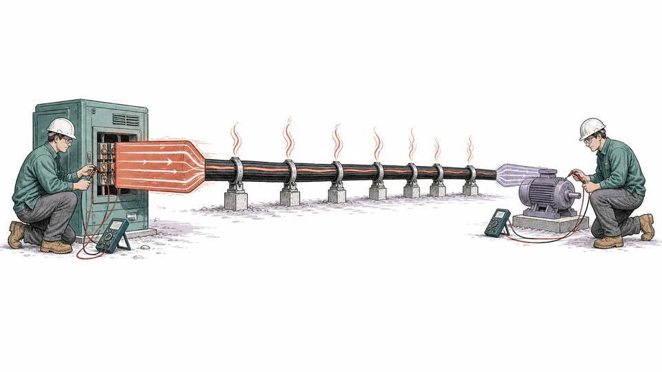
Short high-current peaks can dominate heating even when average energy efficiency looks favorable.
Engineering
Estimate real power delivered through a cable circuit, conductor I²R loss, efficiency, voltage drop, and annual loss energy from one measured operating point.
FEEDER ENERGY BALANCE
This page helps energy engineers and electrical designers quantify how much measured source power is lost as conductor heat at one steady operating condition. It calculates phase-correct real input power, temperature-basis conductor resistance entered by the user, I²R loss across loaded conductors, delivered real power, voltage drop, and annual loss energy. It does not replace an ampacity or thermal model; it makes the energy balance explicit.
FEEDER ENERGY BALANCE
Efficiency is meaningful only when all measurements describe the same steady state and resistance uses the same temperature and AC/DC basis as the circuit. Compare loss energy with the cost and feasibility of a larger conductor or shorter route, not with an arbitrary universal efficiency target.
| Energy-balance step | Electrical measurement | Path model | Time basis | Calculated outcome |
|---|
CURRENT CALCULATION PROCESS
Psource = kphaseVI PF; Rpath = RacL / (1000nruns); Ploss = nconductorsI²Rpath; ηcable = (Psource − Ploss) / Psource
The calculator uses simultaneous voltage, current, and power factor to establish source real power. It treats the entered resistance as the effective resistance of one conductor at operating condition, divides it across parallel paths, and applies I²R to every loaded conductor.
Intermediate values remain unrounded until display formatting.
HOW TO USE THIS MODEL
FEEDER ENERGY BALANCE FUNDAMENTALS
MODEL AND FORMULA
The calculator uses simultaneous voltage, current, and power factor to establish source real power. It treats the entered resistance as the effective resistance of one conductor at operating condition, divides it across parallel paths, and applies I²R to every loaded conductor.
SYMBOLS AND DEFAULT CASE
| Symbol or input | Meaning | Unit or default |
|---|---|---|
| P_source | Source real power | kW |
| k_phase | Phase multiplier: 1 or sqrt(3) | dimensionless |
| R_path | Equivalent resistance of one loaded path | ohm |
| R_ac | Entered conductor resistance | ohm/km |
| P_loss | Conductor heat loss | kW |
| eta_cable | Delivered power divided by source power | dimensionless |
| phases | Circuit phases (1 or 3) | 3 |
| voltageV | Source voltage (V) | 400 |
| currentA | Line current (A) | 185 |
| powerFactorPercent | Power factor (%) | 90 |
| lengthM | One-way route length (m) | 180 |
| resistanceOhmPerKm | Conductor resistance (ohm/km) | 0.153 |
| parallelRuns | Parallel runs | 2 |
| operatingHours | Annual operating hours | 4200 |
Percent inputs are converted to decimal factors once. The live calculation process above substitutes the current values in order, names intermediate quantities, reports the final result, and closes with a reverse or conservation check.
DEEP ENGINEERING ANALYSIS
Short high-current peaks can dominate heating even when average energy efficiency looks favorable.
Higher conductor temperature raises resistance, which raises loss and may increase temperature again until the installation reaches equilibrium.
Skin effect, proximity effect, harmonics, and neutral current can make effective AC loss exceed a simple DC-resistance estimate.
WORKED DECISION CASES
An energy team compares measured loss against a larger parallel feeder. The saving uses interval currents, actual cable temperature, and outage cost rather than extrapolating one noon reading.
The feeder appears efficient at rated load, but harmonic current and neutral heating require an AC-resistance and power-quality assessment beyond the simple balanced model.
TECHNICAL GLOSSARY
EVIDENCE AND DATA LINEAGE
Keep meter timestamps and accuracy, phase configuration, voltage and current RMS definitions, power-factor method, cable material and size, AC/DC resistance basis and temperature, measured or estimated conductor temperature, route length, parallel-run equality, operating-hour profile, and the unrounded energy balance.
LIMITS AND EXCLUSIONS
RELIABLE SOURCES
FREQUENTLY ASKED QUESTIONS
Each current-carrying path dissipates I²R heat; a balanced three-phase set has three loaded phase conductors.
No. Voltage drop is a voltage-quality metric; efficiency compares real power delivered with real power supplied.
Only as a preliminary screen. Operating-temperature AC resistance is a better basis for an energized cable.
The tool assumes those hours occur near the entered current; a varying load should be integrated interval by interval.
At the same total current, two equal paths halve equivalent resistance and therefore modeled loss, provided current sharing is equal.
No. The page rejects a loss equal to or greater than source real power because that indicates inconsistent inputs or units.
IMPORTANT ENGINEERING NOTE
Before changing a cable or operating limit, a qualified electrical professional should verify the measurement boundary, conductor temperature, AC resistance, power quality, installation thermal conditions, applicable code, protective devices, fault withstand, and equipment voltage requirements.