Physics and mechanics
Heat Transfer Rate Calculator
Calculate signed steady heat-transfer rate, heat flux, and overall conductance from U-value, area, and boundary temperatures, with power kept distinct from energy.
CURRENT MODEL
Enter the declared thermal case
HVAC, process, equipment, and building-envelope users screening a steady thermal load from a known overall heat-transfer coefficient.
Decision supportedEstimate the steady heating or cooling duty associated with a declared U-value, effective area, and driving temperature difference.
LIVE THERMAL ANALYSIS
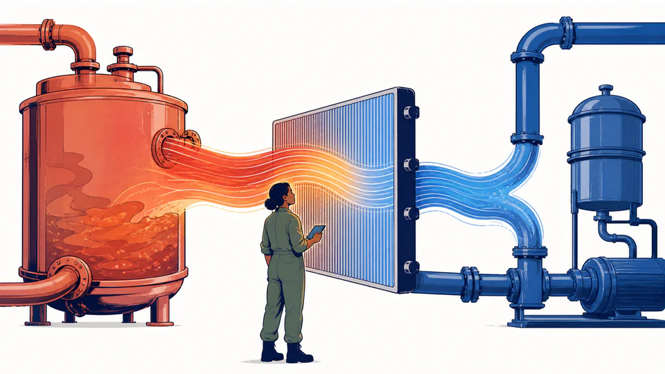
Driving temperature difference and steady heat flow
The live arrow reverses with the sign of the current temperature difference; its width scales with current rate magnitude and the labels retain watts and W/m2.
| Quantity | Symbol or equation | Current value | Unit |
|---|
How to use
Calculate a declared steady duty
- Obtain an overall U-value that already reflects the intended assembly or exchanger basis.
- Enter the effective area on the same inside, outside, or nominal basis used to define U.
- Enter Boundary A and Boundary B temperatures; the calculator preserves A minus B as the sign convention.
- Confirm that the selected temperature difference is appropriate for the geometry and operating state.
- Read conductance and heat flux with the rate card so an area or U-value basis error is visible.
- Use the result as steady power only; integrate a defensible rate history before reporting energy.
Rate fundamentals
Five quantities must remain distinct
- Overall coefficient U
- Area-normalized conductance including whatever resistances its source declared.
- Conductance UA
- Whole-system W/K response on the entered area basis.
- Temperature difference
- The signed thermal driving force in kelvins.
- Heat-transfer rate
- Energy per unit time, expressed in watts.
- Heat flux
- Rate divided by area, expressed in W/m2.
- Total energy
- The time integral of rate, not an output of this steady calculator.
Calculation method
Multiply conductance by the driving difference
U times area produces overall conductance in W/K. Multiplying that by Boundary A minus Boundary B produces signed watts. Dividing the same rate by area returns U times delta T as heat flux.
Because a Celsius interval and a kelvin interval have the same numeric size, no offset is applied to the difference. Absolute temperature would still be required for radiation or property correlations.
Area-basis discipline
Heat-exchanger U-values may be referenced to inner or outer area. Mixing one basis with another area creates a systematic duty error even when every number looks plausible.
Representative delta T
A single difference fits a wall with near-uniform boundaries. Counterflow and multipass exchangers often need log-mean temperature difference and a correction factor.
Zero and reversal
Equal temperatures produce exactly zero watts. Reversing the order produces a negative signed result and a reversed arrow instead of silently taking an absolute value.
U-value provenance
Fouling, film coefficients, wall layers, bridges, and radiation may or may not be embedded in U. Preserve its derivation before using the result for equipment duty.
Detailed calculation process
Symbols, current substitution, intermediate quantities, and reconciliation
qdot = U A (T_A - T_B); heat flux = qdot/AUnrounded SI values are used throughout. Rate displays to 0.1 W, heat flux to 0.01 W/m2, conductance to 0.01 W/K, and temperature difference to 0.01 K.
| Symbol | Meaning | Default | Unit |
|---|---|---|---|
| U | Overall heat-transfer coefficient | 1.8 | W/(m2 K) |
| A | Effective area on U basis | 25 | m2 |
| T_A / T_B | Boundary temperatures | 35 / 5 | deg C |
| delta T | Signed T_A minus T_B | 30 | K |
| UA | Overall conductance | 45 | W/K |
| qdot | Signed steady rate | 1350 | W |
Waiting for valid inputs.
Evidence and measurement
Freeze the U-value and temperature basis
Retain the U-value source, test standard or correlation, area basis, fouling state, flow rates, fluid properties, and mean temperatures. Record where each boundary temperature was measured and whether it is bulk, surface, inlet, outlet, or an approved mean.
Scope and limitations
What qdot = U A delta T does not resolve
- Transient heat storage and startup
- Temperature-dependent U or changing flow regime
- Log-mean temperature difference or exchanger correction factors
- Radiation, phase change, reaction heat, and internal generation unless embedded in U
- Fouling growth, bypass leakage, and maldistribution
- Equipment capacity, controls, redundancy, and safety margins
Steady state; one effective U-value based on the entered area; uniform representative temperature difference; constant properties; no fouling drift, radiation correction, thermal bridging, heat storage, or phase change unless already embedded in U.
Key terminology
Steady-rate glossary
- U-value
- Overall area-normalized heat-transfer coefficient.
- Conductance
- Heat-transfer rate per kelvin for the complete entered area.
- Driving force
- The temperature difference that causes the modeled transfer.
- Heat flux
- Rate per area, used to compare surface loading.
- Steady state
- A condition with no modeled energy accumulation.
- Area basis
- The geometric reference on which U is defined.
- Fouling
- Deposits that add resistance and reduce effective U.
- LMTD
- Log-mean temperature difference used for changing exchanger temperature gaps.
Practical cases
Two uses with different temperature evidence
Envelope heat-loss screen
A designer uses a tested assembly U-value, net wall area, and indoor-outdoor design temperatures. The rate supports load screening, while bridges, infiltration, and solar gains remain separate.
Exchanger duty checkpoint
An operator enters an approved effective U and representative delta T for one stable operating point. A changing inlet-outlet profile requires an LMTD or distributed calculation instead.
Important note
Do not multiply by an arbitrary duration
A steady point can overstate or understate actual energy if temperatures or U vary. Use measured intervals or a transient model before converting watts to joules or kilowatt-hours.
Frequently asked questions
Why does the result use watts instead of joules?
U A delta T produces energy per unit time. One watt equals one joule per second. A duration and a valid rate history would be required to convert this result into total energy.
What happens when both boundary temperatures are equal?
The driving temperature difference is zero, so the modeled steady rate and heat flux are exactly zero. The U-value and area still define conductance, but there is no thermal driving force.
Can the heat-transfer rate be negative?
Yes. The sign follows Boundary A minus Boundary B. A negative result means the modeled flow direction is from Boundary B toward Boundary A; the magnitude remains positive.
Can I use an R-value instead of U?
Only after matching bases. For an area-normalized assembly resistance R-area in m2 K/W, U = 1/R-area. A total resistance in K/W is not inverted to an area-based U without accounting for area.
Does U include convection and conduction?
It can, if the source that supplied U combined the relevant films, wall layers, fouling, and area basis. This calculator does not reconstruct or verify those components.
Should I use arithmetic mean temperature difference for a heat exchanger?
Not automatically. Many exchangers require a log-mean temperature difference, correction factor, or distributed model. Use this page only when the entered delta T is the governing representative difference.
Authority and follow-on work
Reliable sources and related calculators
- U.S. DOE heat-transfer handbookSteady heat-transfer rate and governing conduction/convection parameters.
- MIT heat-transfer equation sheetHeat-transfer equations and thermal-resistance basis.
- NIST Guide to the SIWatt, joule, heat flux, and coefficient units.
Related calculators
Continue with a distinct heat-transfer question without silently changing the model boundary.