Physics and mechanics
Heat Transfer Solver Calculator
Solve a one-layer steady-state heat-transfer network for heat rate, required conductivity, or required thickness with convection films and an auditable resistance ledger.
CURRENT MODEL
Enter the declared thermal case
Mechanical, building-envelope, and process engineers screening a plane-wall assembly before detailed simulation or code review.
Decision supportedDetermine whether a proposed layer and its boundary films meet a heat-flow target, or back-solve the conductivity or thickness needed to meet that target.
LIVE THERMAL ANALYSIS
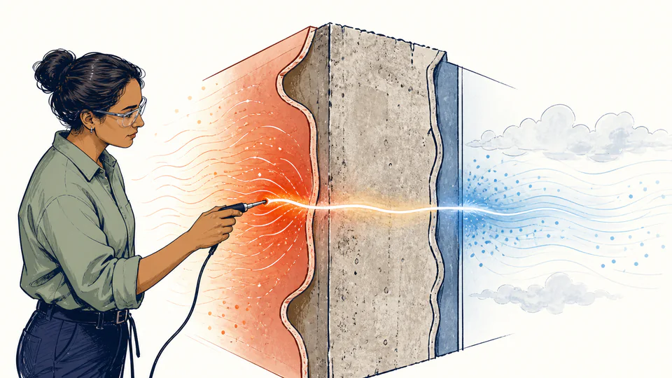
Where the temperature drop occurs
The live resistance strip scales each segment from current film and layer resistances; temperature markers identify both solved wall surfaces.
| Network element | Equation | Current value | Unit |
|---|
How to use
Solve one unknown without hiding the boundary films
- Select heat rate for a forward check, or select conductivity or thickness for an inverse target.
- Enter bulk hot- and cold-fluid temperatures; do not substitute estimated surface temperatures.
- Use convection coefficients tied to the actual flow regime, fluid properties, geometry, and surface condition.
- Enter the plane layer's conductivity, thickness, and normal heat-transfer area on one consistent SI basis.
- For an inverse design, enter a positive target-rate magnitude and inspect whether the fixed films leave any resistance for the layer.
- Read the segment ledger before accepting the solved unknown; a dominant film may make a material change ineffective.
Thermal-resistance fundamentals
Five distinctions that keep the network physical
- Bulk temperature
- The representative fluid temperature away from the wall surface.
- Surface temperature
- The interface value obtained after the convection-film temperature drop.
- Film resistance
- 1/(hA), controlled by convection conditions and area.
- Layer resistance
- L/(kA), controlled by material, thickness, and area.
- Series network
- The same steady heat rate passes through every element while temperature drops add.
- Inverse feasibility
- The target total resistance must exceed the two fixed film resistances.
Calculation method
Turn conduction and convection into one auditable path
The model first calculates each K/W resistance. It sums the two convection films and the plane layer, then divides the signed bulk-temperature difference by the total. In inverse modes, the target rate determines a required total resistance; the fixed films are subtracted before conductivity or thickness is solved.
The surface temperatures are not inputs. They are reconciliations: the hot surface equals the hot bulk temperature minus qdot times the hot film resistance, and the cold surface equals the cold bulk temperature plus qdot times the cold film resistance.
Film-limited design
When 1/(hA) dominates, increasing solid conductivity or reducing thickness produces little rate change. Improve convection or area only after confirming that the coefficient remains valid.
Contact and parallel paths
Bond lines, air gaps, fasteners, and framing can add series or parallel paths. They cannot be represented by silently changing the homogeneous layer conductivity.
Temperature-dependent properties
Conductivity and convection coefficients may change across a wide temperature span. Use representative mean values only for screening; iterate or solve the distributed problem for precision work.
Sign and direction
The forward rate is signed from the hot-labeled side toward the cold-labeled side. A reversed boundary order is preserved rather than converted to an absolute value.
Detailed calculation process
Symbols, current substitution, intermediate quantities, and reconciliation
R_total = 1/(h_hot A) + L/(k A) + 1/(h_cold A); qdot = (T_hot - T_cold)/R_totalAll equations use unrounded SI values. Rates show to 0.1 W, temperatures to 0.01 deg C, and resistances or solved properties to four significant decimal places where practical.
| Symbol | Meaning | Default | Unit |
|---|---|---|---|
| T_hot / T_cold | Bulk boundary temperatures | 120 / 20 | deg C |
| h_hot / h_cold | Convection coefficients | 35 / 12 | W/(m2 K) |
| k | Layer conductivity | 0.8 | W/(m K) |
| L | Layer thickness | 0.05 | m |
| A | Normal area | 2 | m2 |
| R | Total or component resistance | calculated | K/W |
| qdot | Signed steady heat-transfer rate | calculated | W |
Waiting for valid inputs.
Evidence and measurement
Preserve the coefficient and material basis
Save the source, test temperature, moisture state, density, orientation, and aging condition for conductivity. For each convection coefficient, retain the fluid, velocity or flow rate, geometry, characteristic length, surface condition, and correlation or test record. Record whether the area is gross, net, inside, or outside area.
Scope and limitations
What this solver deliberately excludes
- Radiation exchange and solar absorption
- Contact resistance, fouling, gaps, fasteners, and thermal bridges
- Multidimensional edge spreading or cylindrical and spherical geometry
- Transient storage, internal heat generation, and phase change
- Temperature-dependent or anisotropic properties
- Code compliance, condensation, stress, fire, or safety certification
One-dimensional, steady-state heat flow through one homogeneous plane layer with constant properties, uniform area, no contact resistance, no heat generation, and no radiation branch.
Key terminology
Resistance-network glossary
- Conduction
- Heat transfer through a material caused by a temperature gradient.
- Convection film
- The boundary relationship represented by h between a surface and bulk fluid.
- Thermal conductivity
- A material property k describing conductive transport under stated conditions.
- Thermal resistance
- Temperature difference divided by heat rate, expressed in K/W.
- Heat flux
- Heat-transfer rate per unit normal area, W/m2.
- Steady state
- A condition where modeled temperatures no longer change with time.
- Interface temperature
- The temperature where two resistance elements meet.
- Thermal bridge
- A parallel high-conductance path that bypasses the ideal layer.
Practical cases
Two decisions that use different solve modes
Process-vessel insulation screen
An engineer knows surface area, insulation conductivity, fluid temperatures, and both film coefficients. Forward mode shows whether predicted loss fits the utility balance and whether the exterior surface temperature needs a separate personnel-protection review.
Required panel thickness
A cold-room designer sets a maximum conductive-convective load. Thickness mode subtracts the indoor and outdoor film resistances, then solves the remaining layer resistance. Framing bridges and moisture effects still require assembly-level review.
Important note
Do not use the solved thickness as a specification by itself
A feasible arithmetic result does not establish available products, structural performance, condensation control, fire behavior, tolerances, installation quality, or compliance. Preserve the unrounded calculation and obtain a qualified design review before procurement or safety decisions.
Frequently asked questions
Why are there three resistances instead of one U-value?
The separated network shows whether the hot film, solid layer, or cold film controls the result. A single U-value hides that diagnostic information and makes an inverse thickness or conductivity check harder to audit.
Can this solve a multilayer wall?
Not directly. Combine additional plane-layer resistances as L/(kA) only if each layer shares the same one-dimensional area and contact resistance is negligible; otherwise use a dedicated multilayer model.
Why can an inverse solution be physically impossible?
The two convection films impose a minimum resistance. If the target rate demands a total resistance smaller than those fixed films alone, no positive layer thickness or conductivity can satisfy the target under this model.
Does the calculator include radiation?
No. Radiation can be important at high surface temperatures or across gaps. Add an appropriate radiation branch or use a coupled analysis when it is material.
Which temperature should I enter for a fluid?
Enter the bulk fluid temperature associated with the convection coefficient. Do not substitute an already estimated wall-surface temperature, because the model solves those surface temperatures.
Is a negative heat rate an error?
The forward model preserves direction: a hot-side temperature below the cold-side temperature produces a negative signed rate. Inverse modes use a positive target magnitude and require distinct boundary temperatures.
Authority and follow-on work
Reliable sources and related calculators
- U.S. DOE heat-transfer handbookConduction, convection, thermal resistance, and steady-state heat-transfer foundations.
- MIT 2.051 heat-transfer equation sheetPlane-wall Rcond = L/(kA) and convection Rconv = 1/(hA).
- NIST Guide to the SISI units for thermal conductivity, heat flux, energy, and power.
Related calculators
Continue with a distinct heat-transfer question without silently changing the model boundary.