Short exhibit illumination
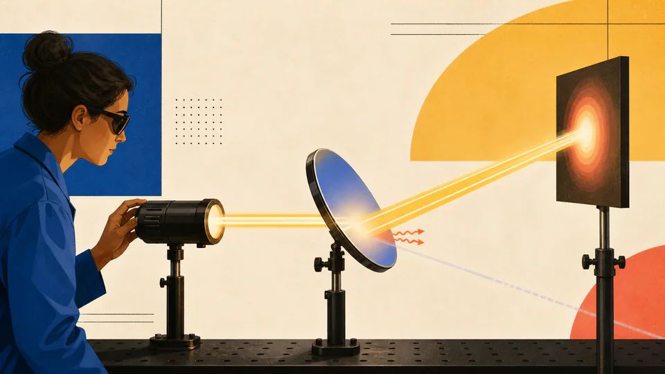
At 800 W/m2 over 0.01 m2, 20 degrees, and 0.25 s, a high-reflectance mirror redirects most intercepted energy while a smaller share enters the coating. The closure remainder identifies energy not described by R or A.
Physics and geometric optics
Calculate incident, reflected, absorbed, and remaining optical energy for a tilted mirror during a finite exposure.
Finite optical exposure budget
This page budgets energy that reaches a finite mirror area during a specified interval. Angle changes how much beam power is intercepted; coating fractions then divide that incident energy into reflected, absorbed, and unaccounted paths.
Current model evidence
Audit geometry, exposure time, and coating partitions as separate current-value steps.
| Energy stage | Primary basis | Secondary basis | Current value | Scope / unit |
|---|
DETAILED CALCULATION PROCESS
Aeff = A cos(theta); Pinc = I Aeff; Uinc = Pinc t; Uref = rho Uinc; Uabs = alpha Uinc
Project the illuminated physical area onto a plane normal to propagation, convert irradiance to intercepted power, integrate over time, and only then apply reflectance and absorptance.
| Symbol | Meaning | Unit | Default basis |
|---|---|---|---|
| I | Average irradiance at mirror | W/m2 | 800 W/m2 |
| A | Illuminated physical area | m2 | 0.01 m2 |
| theta | Angle from surface normal | deg | 20 deg |
| t | Exposure interval | s | 250 ms = 0.25 s |
| rho | Reflectance fraction | 1 | 0.85 |
| alpha | Absorptance fraction | 1 | 0.10 |
HOW TO USE THIS CALCULATOR
MIRROR PHYSICS FOUNDATIONS
DEEP ANALYSIS 1
A coating may remain 85% reflective while less total beam power reaches the physical patch at oblique incidence. Applying one undocumented efficiency loses that distinction.
DEEP ANALYSIS 2
Heating also depends on substrate mass, heat capacity, spatial deposition, convection, conduction, and pulse timing. This page stops at optical energy.
DEEP ANALYSIS 3
Reflected, absorbed, and remaining shares must close to intercepted incident energy. A percentage sum above 100% is physically inconsistent and is rejected.
RESULT INTERPRETATION
Reflected energy is available to the intended or stray reflected path; it is not automatically energy delivered to a target because downstream area and losses are excluded.
Absorbed energy is the optical budget retained by the mirror during the interval, not a thermal damage prediction.
REAL USE CASES
At 800 W/m2 over 0.01 m2, 20 degrees, and 0.25 s, a high-reflectance mirror redirects most intercepted energy while a smaller share enters the coating. The closure remainder identifies energy not described by R or A.
At 90 degrees the ideal projected area is zero, so all energy outputs become zero even with nonzero irradiance. Real edge thickness and diffuse illumination fall outside the planar model.
EVIDENCE AND DATA QUALITY
Retain irradiance measurement method, beam footprint, angle reference, exposure timing, coating datasheet wavelength and angle, surface condition, and the R+A closure used in the exported result.
LIMITS AND EXCLUSIONS
TERMS USED HERE
RELIABLE SOURCES
FREQUENTLY ASKED QUESTIONS
At normal incidence theta = 0 and cos(theta) = 1, so the full illuminated area is presented to the beam.
Yes. A zero-power boundary returns zero incident, reflected, and absorbed energy while preserving valid geometry.
Those are fractions of the same incident budget; a sum above one violates energy conservation.
It is the unassigned remainder and may represent transmission, scattering, or incomplete property data.
Only if the intended question is a constant-power exposure. Pulsed energy requires pulse-resolved timing and peak-damage analysis.
No. Thermal, mechanical, coating-damage, and personnel-safety limits require additional models and authoritative limits.
IMPORTANT BOUNDARY
This idealized optical-energy budget is not a laser-safety calculation, coating-damage certification, thermal design, or radiometric calibration.