p

Physics and geometric optics

Mirror Solver Calculator

Solve the signed spherical-mirror equation for image distance, magnification, image height, and real or virtual image classification.

Paraxial spherical-mirror imaging

Locate and classify one mirror image before you set the bench

This solver answers where a concave or convex spherical mirror places the paraxial image of one real object. Signed distance and signed magnification remain visible so a physically different virtual image cannot masquerade as a positive screen distance.

Signed image distance-
Signed magnification-
Signed image height-
Radius magnitude-

Current model evidence

Signed image-solution ledger

Keep focal sign, image sign, and orientation visible from equation to bench decision.
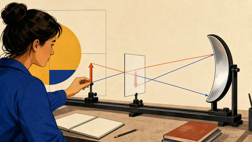
Editorial optics bench with an object, concave mirror, reflected rays, and an inverted image on a movable screen
The screen can capture only a real image; the sign of di distinguishes that outcome before hardware is moved.
Current paraxial image geometryThe live axis places the object, focal point, mirror, and signed image from the current values; dashed extensions identify a virtual image.
Signed image-solution ledgerCurrent unrounded calculation path
Keep focal sign, image sign, and orientation visible from equation to bench decision.
StepInput AInput BCurrent resultScope / unit

DETAILED CALCULATION PROCESS

Formula, units, default substitution, and reconciliation

1. Governing relation

1/f = 1/do + 1/di; di = f do/(do - f); m = -di/do = hi/ho

Apply the real-is-positive mirror convention: concave focal length is positive, convex focal length is negative, a positive image distance is real, and a negative image distance is virtual. Solve the distance first, then use its sign in magnification.

2. Symbols and default basis

SymbolMeaningUnitDefault basis
fSigned focal lengthcm+20 cm for concave
doPositive real-object distancecm60 cm
diSigned image distancecmSolved
mSigned lateral magnification1Solved
hoPositive object heightcm5 cm
hiSigned image heightcmm ho

3. Unit and sign normalization

  • Every length uses centimetres, so the mirror equation is unit-consistent without conversion.
  • The focal-length field is a magnitude; mirror type supplies plus for concave and minus for convex.
  • A negative hi means the image arrow is inverted relative to the positive object arrow.

4. Current numerical substitution

    5. Independent reconciliation

    HOW TO USE THIS CALCULATOR

    Five steps from measured inputs to a defensible result

    1. Choose concave or convex before entering a focal magnitude; do not type a negative focal value.
    2. Measure object distance from the mirror vertex, not from the focal point or rim.
    3. Enter the upright object height using the same length unit as the distance fields.
    4. Read signed image distance before deciding whether a physical screen can intercept the image.
    5. Use the reciprocal and height-ratio checks in the export to catch sign or transcription errors.

    MIRROR PHYSICS FOUNDATIONS

    Concepts that control this specific model

    The vertex is the distance origin
    Object and image distances are measured from the point where the optical axis meets the mirror.
    Concave and convex focal signs differ
    A concave mirror converges paraxial rays and uses f > 0; a convex mirror diverges them and uses f < 0.
    Real images have positive di
    Reflected rays actually meet in front of the mirror and can be projected onto a screen.
    Virtual images have negative di
    Reflected rays diverge but their backward extensions meet behind the mirror; no screen placed there captures them.
    Magnification carries orientation
    The magnitude |m| gives scale while the sign distinguishes upright from inverted.

    DEEP ANALYSIS 1

    The focal point is a genuine singular boundary

    For a concave mirror at do = f, reflected paraxial rays are parallel. A finite di is undefined, so the calculator reports an error instead of an enormous rounded distance.

    DEEP ANALYSIS 2

    Object position controls the concave image regime

    Beyond 2f the image is real and reduced; at 2f it is same-size; between f and 2f it is real and enlarged; inside f it is virtual, upright, and enlarged.

    DEEP ANALYSIS 3

    Paraxial accuracy is an aperture decision

    The equation assumes rays near the optical axis. A wide spherical mirror can show spherical aberration, so a calculated point may become a blur region in a real setup.

    RESULT INTERPRETATION

    What the current output does and does not decide

    Positive di means a screen may be placed that many centimetres in front of the mirror; negative di locates a virtual image behind the mirror for an observer.

    A value m = -0.5 means an inverted image at half the object height; m = +2 means an upright virtual image twice as tall.

    REAL USE CASES

    Two decisions with different boundary conditions

    Projecting a reduced demonstration image

    A 20 cm concave mirror with an object at 60 cm gives di = 30 cm and m = -0.5. Place a screen near 30 cm and expect an inverted image about 2.5 cm tall for a 5 cm object.

    Checking a convex safety mirror

    With the same 20 cm magnitude and 60 cm object distance, the convex sign gives di = -15 cm and m = +0.25. The smaller upright image is virtual and cannot be projected behind the coated surface.

    EVIDENCE AND DATA QUALITY

    What to retain with the exported result

    Retain the mirror type, manufacturer focal tolerance, vertex-to-object measurement, object height, aperture used, and whether a screen or visual observation confirmed the predicted sign regime.

    LIMITS AND EXCLUSIONS

    Where this physical model stops

    • Applies to spherical mirrors under the paraxial approximation.
    • Assumes one real object with positive object distance.
    • Does not model spherical aberration, coma, diffraction, or finite aperture.
    • Does not predict brightness, reflectance, wavelength response, or image contrast.
    • A physical mirror thickness or mounting offset must be handled in the measured vertex position.

    TERMS USED HERE

    Six terms that keep the calculation unambiguous

    Optical axis
    Reference line through the mirror vertex and centre of curvature.
    Focal length
    Signed vertex-to-focus distance for paraxial rays.
    Image distance
    Signed vertex-to-image distance after reflection.
    Real image
    Image formed by actual convergence of reflected rays.
    Virtual image
    Image located by backward extensions of diverging reflected rays.
    Lateral magnification
    Signed ratio of image height to object height.

    RELIABLE SOURCES

    References supporting the equation and units

    FREQUENTLY ASKED QUESTIONS

    Questions specific to this calculation

    Why does a convex mirror return a negative image distance?

    Its reflected rays diverge. Their backward extensions meet behind the mirror, which the sign convention records as negative di.

    Can I type a negative focal length?

    No. Choose mirror type and enter a positive magnitude so focal sign is assigned once, visibly, and consistently.

    Why is do = f rejected for a concave mirror?

    The paraxial image is at infinity, so no finite result card or screen position exists.

    Does a negative image height mean a negative physical size?

    No. Magnitude is the size; the negative sign records inversion relative to the chosen upright direction.

    Can this solve a plane mirror?

    A plane mirror is the infinite-radius limit, not a finite focal-length input on this page.

    Why might my screen image be blurred at the calculated position?

    Finite aperture, alignment, surface error, and spherical aberration spread rays around the paraxial prediction.

    IMPORTANT BOUNDARY

    Use the result as analysis, not certification

    This paraxial calculation supports education and first-order optical layout; it is not a lens-design certification, metrology report, or safety approval.