p

Physics and geometric optics

Mirror Scenario Calculator

Compare two spherical-mirror choices for the same object, including signed image location, magnification, orientation, and screen feasibility.

Two-mirror decision comparison

Compare two mirror outcomes on one controlled object basis

This calculator keeps object geometry fixed while solving two mirror choices independently. It then compares scale and screen feasibility without turning virtual-image distance into a false screen location.

Scenario A image distance-
Scenario B image distance-
Scenario A magnification-
Absolute scale ratio A/B-

Current model evidence

Controlled mirror-comparison ledger

Solve each mirror independently, then compare image scale and whether a real image fits the entered screen limit.
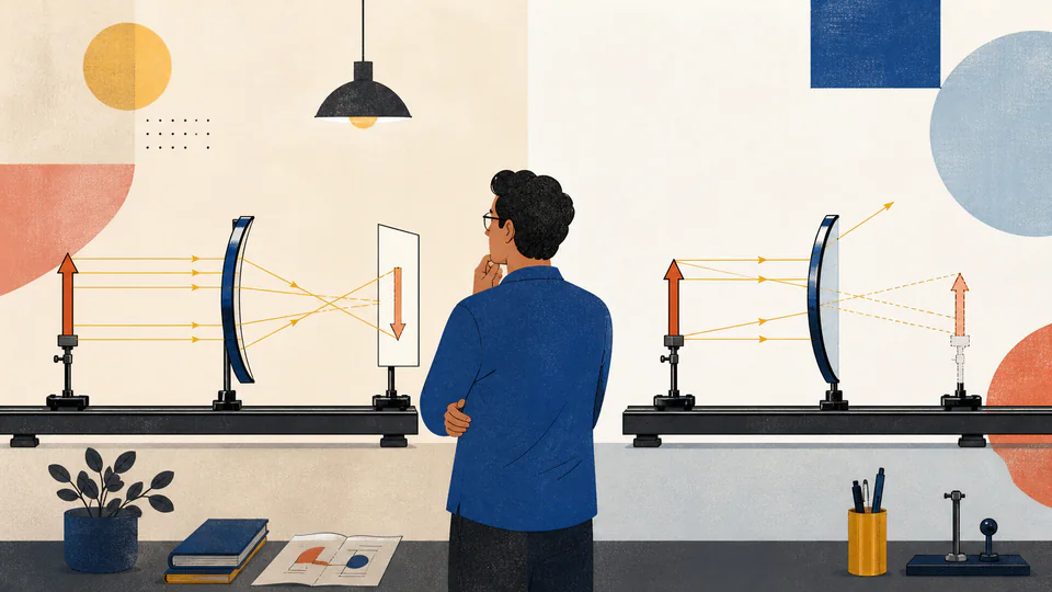
Editorial split optical lab comparing a concave mirror with a real inverted screen image and a convex mirror with a smaller upright virtual image
The same object can yield a projectable real image in one scenario and an unprojectable virtual image in another.
Side-by-side current image geometryEach axis uses the shared object basis but its own signed focal length and image result; the screen limit is marked only as a layout constraint.
Controlled mirror-comparison ledgerCurrent unrounded calculation path
Solve each mirror independently, then compare image scale and whether a real image fits the entered screen limit.
Scenario / comparisonInput or typeSigned distance / scaleCurrent resultDecision state

DETAILED CALCULATION PROCESS

Formula, units, default substitution, and reconciliation

1. Governing relation

For j in {A,B}: dij = fj do/(do - fj), mj = -dij/do, hij = mj ho; feasiblej = (dij > 0 and dij <= Lscreen)

Assign a focal sign for each mirror, solve the two mirror equations separately, classify each signed result, then compare absolute scale and screen feasibility on the shared object and layout basis.

2. Symbols and default basis

SymbolMeaningUnitDefault basis
doShared real-object distancecm75 cm
hoShared upright object heightcm6 cm
fA, fBSigned scenario focal lengthscm+25 cm; -25 cm
diA, diBSigned scenario image distancescmSolved separately
mA, mBSigned scenario magnifications1-di/do
LscreenMaximum allowed real-image distancecm120 cm

3. Unit and sign normalization

  • All object, focal, image, and screen distances use centimetres.
  • Each mirror-type control assigns its own focal sign; both entered magnitudes stay positive.
  • Absolute scale ratio compares |mA| with |mB|, while the signed values remain available for orientation.

4. Current numerical substitution

    5. Independent reconciliation

    HOW TO USE THIS CALCULATOR

    Five steps from measured inputs to a defensible result

    1. Enter one real-object distance and height that both candidate mirrors will share.
    2. Set the farthest usable screen location measured from each mirror vertex.
    3. Choose mirror type and positive focal magnitude independently for scenario A and B.
    4. Read signed image positions and orientations before considering the scale ratio.
    5. Use screen feasibility only for positive di; retain packaging, aperture, and brightness constraints separately.

    MIRROR PHYSICS FOUNDATIONS

    Concepts that control this specific model

    A controlled comparison shares the object basis
    Changing the object between scenarios would mix mirror choice with setup change.
    Each focal sign is independent
    Two mirrors with the same focal magnitude can produce opposite-sign image locations if one is concave and one convex.
    Only real images reach a screen
    A virtual image behind a mirror can be seen by an observer but not intercepted at that signed location.
    Screen limit is a packaging constraint
    It does not alter the optical equation; it classifies an already-solved positive image distance.
    Scale ratio discards orientation on purpose
    Absolute magnification answers which image is larger; signed magnification separately records upright or inverted.

    DEEP ANALYSIS 1

    Feasibility follows physics, then layout

    The calculator first asks whether di is positive. Only then does it compare di with the available screen distance, preventing a negative virtual distance from passing a naive numerical limit.

    DEEP ANALYSIS 2

    Same focal magnitude does not mean same role

    A +25 cm concave mirror can form a real inverted image for a distant object; a -25 cm convex mirror gives a reduced upright virtual image.

    DEEP ANALYSIS 3

    A winner needs more than one metric

    A larger or screen-feasible image may still be too dim, aberrated, narrow in field, expensive, or mechanically incompatible. The comparison deliberately reports but does not invent those criteria.

    RESULT INTERPRETATION

    What the current output does and does not decide

    A positive scenario distance within the limit identifies a first-order screen location. A negative distance means the scenario is virtual regardless of its absolute numeric size.

    Absolute scale ratio above one means A has the larger image magnitude; consult signed mA and mB in the ledger for orientation.

    REAL USE CASES

    Two decisions with different boundary conditions

    Projection versus wide-angle viewing

    With do = 75 cm and equal 25 cm magnitudes, the concave option forms a real inverted image at 37.5 cm while the convex option forms a smaller upright virtual image at -18.75 cm.

    Two concave candidates under a short enclosure

    A shorter-focal mirror may fit a 40 cm screen envelope while a longer-focal mirror produces a real image beyond it. Both are optically valid, but only one meets that packaging constraint.

    EVIDENCE AND DATA QUALITY

    What to retain with the exported result

    Retain object and screen-limit measurement origins, both mirror identifiers and focal tolerances, sign convention, aperture used, predicted screen states, and observed image orientation for each trial.

    LIMITS AND EXCLUSIONS

    Where this physical model stops

    • Compares only paraxial spherical-mirror image geometry.
    • Assumes both scenarios use the same positive real-object distance and height.
    • Screen feasibility ignores screen size, tilt, depth, and mechanical clearance.
    • Does not compare brightness, reflectance, field of view, aberration, wavelength, cost, or durability.
    • A scenario at its concave focal point is rejected because its image is not finite.

    TERMS USED HERE

    Six terms that keep the calculation unambiguous

    Controlled basis
    Inputs deliberately held identical across alternatives.
    Scenario
    One mirror type and focal-length choice solved independently.
    Screen feasibility
    Real positive image distance that also falls within the entered layout limit.
    Signed magnification
    Scale with orientation retained in the sign.
    Absolute scale ratio
    Ratio of image-size magnitudes with orientation removed.
    Packaging constraint
    Physical layout limit applied after the optical solution.

    RELIABLE SOURCES

    References supporting the equation and units

    FREQUENTLY ASKED QUESTIONS

    Questions specific to this calculation

    Why is the object distance shared?

    It isolates the effect of mirror choice; otherwise differences could come from moving the object.

    Can scenario A and B use different mirror types?

    Yes. That is a central use case, and each choice assigns its own focal sign.

    Why is a virtual image never screen-feasible?

    Its rays do not actually converge behind the mirror, so a screen there does not receive the image.

    Can both scenarios be screen-feasible?

    Yes, if both produce positive image distances no greater than the entered limit.

    What if absolute scale ratio is less than one?

    Scenario A produces the smaller image magnitude; signed magnifications still determine each orientation.

    Does this choose the better mirror automatically?

    No. It resolves image geometry and one screen limit; other optical, mechanical, safety, and cost criteria remain external.

    IMPORTANT BOUNDARY

    Use the result as analysis, not certification

    This comparison is a first-order paraxial decision aid, not a complete optical trade study, tolerance analysis, or equipment certification.